We reserve the right to change designs and technical specifications of our products.
13
ENG
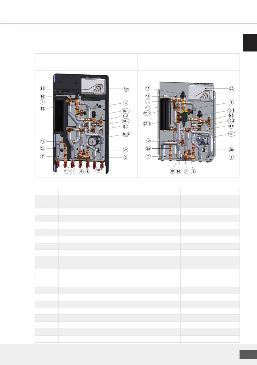
3.3 Design and components
example representations:
LogoMatic G2 MC-UC, insulated version
e.g. with optional ball valves
LogoMatic G2 MC-UC, steel version
e.g. as DWC version
Legend
No. Components Comment
1 Plate heat exchanger, stainless steel, copper soldered/copper
soldered and sealed
24 / 40 /60 plates
2a Adaptor for the cold water meter (L = 110 mm, 2 x ¾" MT)
2b Adaptor for the heat meter (L = 110 mm, 2 x ¾" MT)
3 Insulated stainless steel corrugated pipe
4 Dirt trap, sealed with plug
6 Dierential pressure regulator DN15 (5-25 kPa) Kvs=1.6
7 Cold water connection to dwelling
8 Thermostatic circulation bridge, adjustable from 35 °C to 65 °C for heat retention function
9.1 / 9.2 Lower part of control valve ¾", depending on variant for MC/UC Zone valves for dwelling
heating circuits
10 Mixed circuit with (10.1) motorised control valve, type Mut
VDE ML and (10.2) backflow preventer (BP) and (10.3) HE
pump type GF UPM3 hybrid 15-70 130
(10.2), (10.3) only for MC
variants
11 Control valve, type Mut, VDE ML with servomotor
12 Flow sensor ¾", type Sika VTY10 1 - 30 l/min
13 Flow controller, depending on variant (not available with L-Line)
14 Bleeding/drainage plugs ½" heating-system side
18 M10x1 coupler for heat meter immersion sleeve f. optional. HFM
20 Shut-o ball valve ¾" (union nut x ¾" FT) item-specific equipment
21 (21.1) Domestic water circulation pump with (21.2) BP item-specific equipment
22 Control and switching module LogoTronic HIU controller