M3401-02en Edition 09/2022 21
Description
3
The N-BIPEX couplings described here are universally applicable, torsionally flexible claw
couplings that are available in various types and sizes. They are characterised by a very
compact design. The couplings can be used in accordance with the Explosion Protection Dir-
ective in potentially explosive atmospheres if they have a corresponding marking.
N-BIPEX couplings are fail-safe.
These instructions describe the assembly and operation of a N-BIPEX coupling arranged ho-
rizontally with a shaft-hub connection made by a cylindrical or conical bore with parallel key,
or with TAPER clamping bush with parallel key. Please consult Flender if you want to use a
different type of installation.
Application
N-BIPEX couplings are suitable for drives with a uniform torque load and low misalignment.
Structure
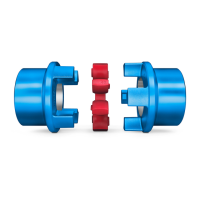
A N-BIPEX coupling consists of two hub parts that are connected to one another by a cam
ring made of an elastomer material. The hub parts are joined to the shaft by finished bores
with a parallel key or by TAPER clamping bushes with a parallel key. The three different
types are differentiated by combination of these two options.
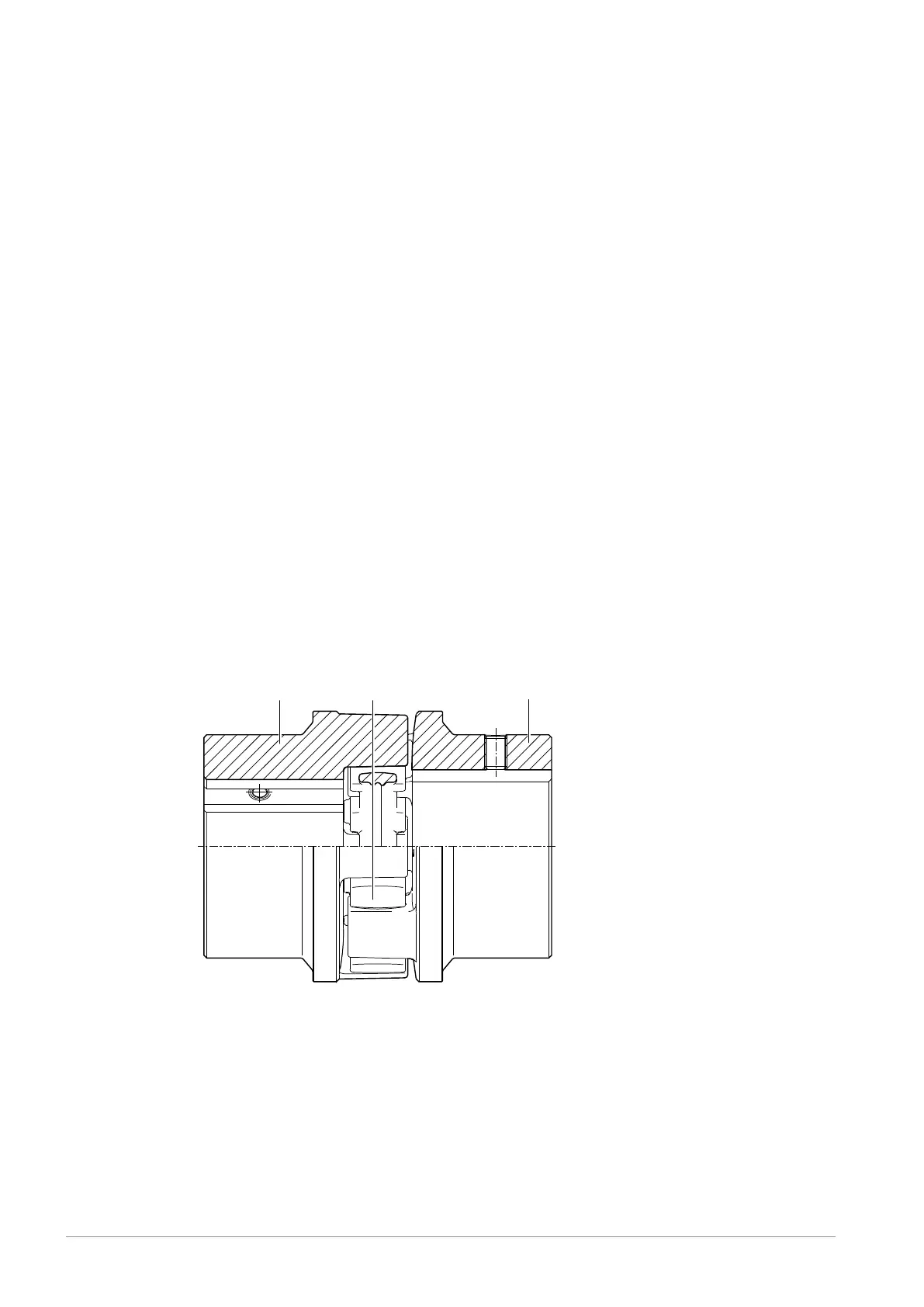
The diagrams show the various types with their constituent parts and their part numbers.
Figure3-1:BWN type
1 Coupling part 1/2
2 Coupling part 1/2
50 Cam ring



 To Next Page