Assembly
5.1 Preparatory work
M3401-02en Edition 09/2022 29
Selection of the set screw
CAUTION
Physical injury
Danger of injury from protruding set screw.
• Please observe the information about selecting the set screw.
Use set screws in accordance with ISO4029 with a toothed cup point. The size of the set
screw is determined by the bore made. The set screw should fill out the threaded hole as
much as possible and must not protrude beyond the hub.
5.1.4 Balancing the coupling5.1 Preparatory work
Notes on balancing the coupling
NOTICE
Property damage to coupling part 1/2 (1 or 2)
If you completely drill through the base on coupling part 1/2 (1 or 2), then coupling part 1/2
(1 or 2) is no longer allowed to be used for operation.
• Please observe the stipulations about machining the balancing bore.
Please note the following when balancing the coupling:
• Select the balancing quality according to the application (but at least G16 in accordance
with DINISO21940).
• Observe the balancing specification according to DIN ISO 21940-32.
• Machine the balancing bore on a large radius with adequate clearance to the cams and
the outer circumference.
• Carefully deburr the balancing bore.
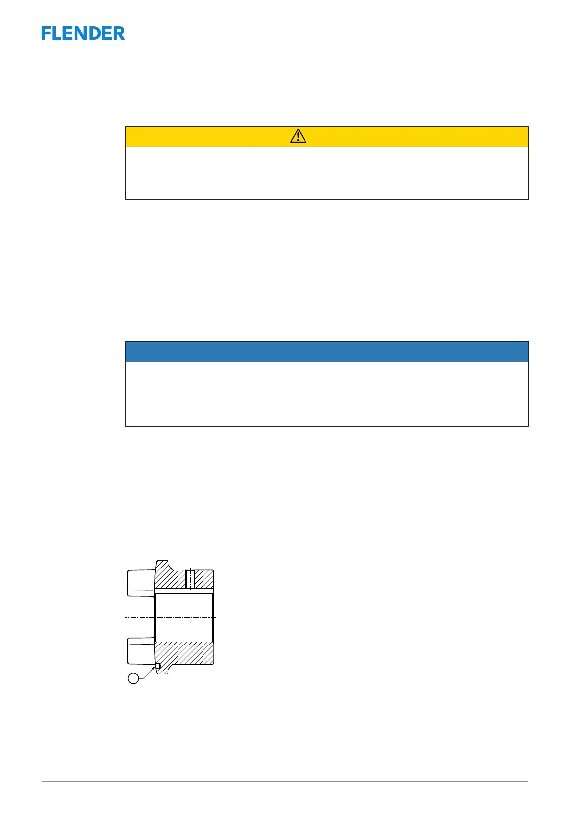
Figure5-3:Position of the balancing bore for single-plane balancing
① Balancing bore