Assembly
5.1 Preparatory work
M3401-02en Edition 09/2022 27
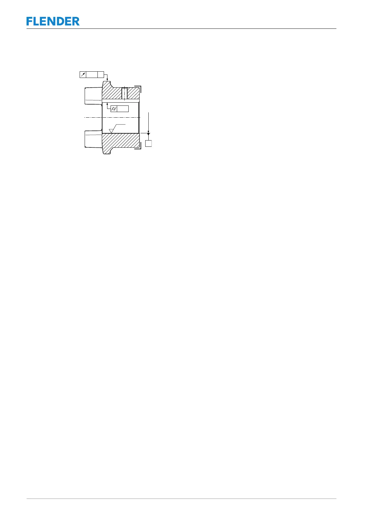
Figure5-1:Tolerances for the finished bore in coupling part 1/2 (1 or 2)
5.1.2 Milling the parallel keyway5.1 Preparatory work
Position of the parallel keyway
Arrange the parallel keyway in the centre between the cams.
Applicable standards
• If the coupling is intended for use under normal operating conditions, mill the parallel
keyway according to DIN6885/1ISOJS9.
• If the coupling is intended for reversing operation, mill the parallel keyway according to
DIN6885/1ISOP9.
• If you want to mill a parallel keyway that does not correspond to DIN6885/1, please con-
sult Flender.
5.1.3 Machining an axial locking mechanism5.1 Preparatory work
The coupling part 1/2 (1 or 2) is secured by a set screw or an end plate to prevent axial
movements.
Please consult Flender if you want to use an end plate.
Note the following when using a set screw:
• Diameter and axial position of the tapped hole in the hub
• Position of the tapped hole with respect to the parallel keyway
• Selection of the set screw