Assembly
5.2 Assembling the coupling
30 Edition 09/2022 M3401-02en
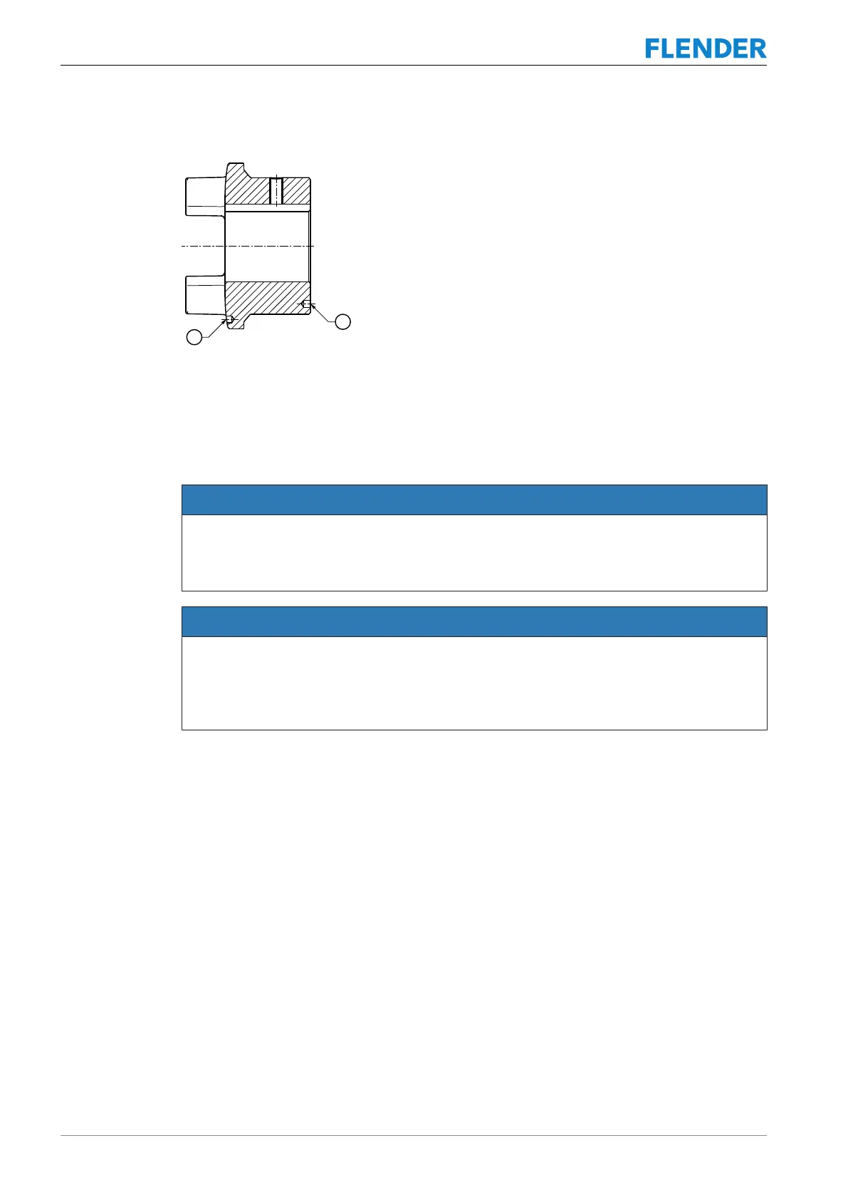
Figure5-4:Position of the balancing bore for two-plane balancing
① Balancing bore
5.2 Assembling the coupling5.2 Assembling the coupling
NOTICE
Property damage
Damage to the elastomer components from cleaning agents.
• Ensure that the elastomer components do not come into contact with cleaning agents.
NOTICE
Property damage
Damage to the shaft end, the coupling parts, the TAPER clamping bush and/or the parallel
key.
• Note the handling instructions regarding assembly of the coupling parts.
The assembly procedure depends on which coupling part you wish to assemble.
• The coupling parts 1/2 (1 and 2) with coupling types BWN and BNT are mounted on the
shaft by means of a parallel key.
• The coupling parts 3 (3) and 4 (4) with coupling types BWT and BNT are mounted on the
shaft with TAPER clamping bushes with parallel key.
5.2.1 Installing coupling part 1/2 (1 or 2)5.2 Assembling the coupling
Procedure
1. Unscrew the set screw out of coupling parts 1/2 (1 and/or 2) until it is no longer possible
for there to be a collision with the parallel key or the shaft.
2. Clean the bores and shaft ends.
3. Coat the bores of the coupling parts1/2(1 and/or 2) and the shafts with MoS
2
assembly
paste (e.g. MicrogleitLP405).