Assembly
5.2 Assembling the coupling
M3401-02en Edition 09/2022 31
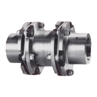
4. Mount the coupling part1/2(1 and/or 2) on the shaft.
WARNING
Danger due to bursting of the coupling
If you do not observe the information stipulated here when assembling coupling parts with
a tapered bore, then this can cause the coupling to burst in operation. There is a risk of
fatal injury from flying fragments. If a coupling bursts in an area at risk of explosion, then
this can result in an explosion.
• Mount the coupling parts 1/2 (1 and/or 2) with conical bore and parallel keyway on the
shaft in cold condition. Secure the coupling parts with suitable end plates without
pulling the coupling parts further onto the cone (fitting dimension=0).
Information
Coupling parts with cylindrical bore
To make assembly easier, you can heat coupling part 1/2 (1 or 2) with cylindrical bore up to
a maximum of 120°C if required. Note when doing this the temperature range of the cam
ring(50) (see section N-BIPEX cam ring (50) (Page63)). Remove the cam ring(50) where
appropriate. Protect adjacent components against damage and heating to temperatures
above 80°C.
5. Secure the coupling parts 1/2 (1 and 2) with a set screw or an end plate. When securing
with a set screw the shaft must not protrude or be set back from the inner side of the
hub.
6. Tighten up the set screw or the screw to attach the end plate to the specified tightening
torque T
A
(for the set screw please see section Machining an axial locking mechanism
(Page27)).
7. If you have removed the cam ring(50), re-fit the cam ring(50).
5.2.2 Assembling coupling part 3 (3) or 4 (4)5.2 Assembling the coupling
DANGER
Danger of explosion
Improper operation of the coupling can lead to an explosion in potentially explosive atmo-
spheres.
• Make sure that a parallel key has been inserted in the shaft.
• Apply a small quantity of liquid screw locking agent (e.g. Loctite 243, medium strength)
to the threads of the screws for the TAPER clamping bush(101), (102).
Procedure
1. Clean the bores, the shaft ends and the TAPER clamping bush (101), (102). The large
front face of the TAPER clamping bush (101), (102) has two axis-parallel half blind holes
up to size 3030 and three in the case of size 3535 and larger. The coupling part 3 (3) or
4 (4) has half tapped holes in the same angular position.
2. Insert the TAPER clamping bush (101) or (102) in the coupling part 3(3) or 4(4).