Servicing
8.2 Maximum permissible torsional backlash
44 Edition 09/2022 M3401-02en
8.2 Maximum permissible torsional backlash8.2 Maximum permissible torsional backlash
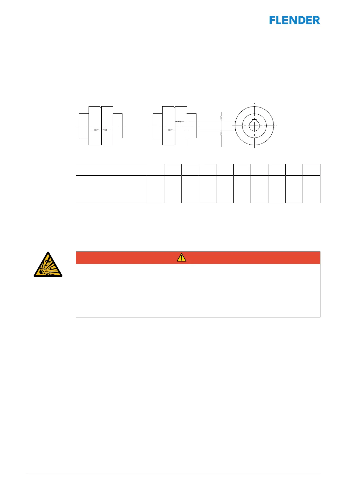
In order to calculate the torsional backlash, rotate one coupling part without applying torque
up to the stop. Mark both of the coupling halves in the way shown in the diagram below. Turn
the coupling part in the opposite direction up to the stop. The markings on both halves will
then move apart. The distance between the markings corresponds to the torsional backlash.
Figure8-1:Markings for calculating the torsional backlash
Size 19 24 28 38 42 48 55 65 75 90
Maximum permissible
torsional backlash ∆S
V
[mm]
2.5 3.5 4.5 5.5 6.5 7 8 9 11 13.5
Table8-2: Maximum permissible torsional backlash
8.3 Replacing wearing parts8.3 Replacing wearing parts
DANGER
Danger due to bursting of the coupling
If you do not observe the information stipulated here regarding replacement of wearing
parts, this can lead to bursting of the coupling during operation. There is a risk of fatal in-
jury from flying fragments. Bursting of the coupling can lead to an explosion in potentially
explosive atmospheres.
• Please observe all the stipulations concerning the replacement of wearing parts.
Replace the cam ring (50) if the maximum permissible torsional backlash has been reached.
Procedure
1. Move the coupled machines apart.
2. Remove the cam ring(50).
3. Insert the new cam ring(50).
Please observe the information in section Use and storage of the cam rings (Page63).
When reinstalling the coupling parts please observe the information in chapters Assembly
(Page25) and Commissioning (Page35).