Technical data
Speeds, geometry data and weights
M3401-02en Edition 09/2022 59
Size Speed
n
max
rpm
D1 D2 DA
mm
ND1
mm
ND2
mm
NL1
mm
NL2
mm
D3
mm
DE
4)
mm
S
mm
S2
TAPER-
clamp-
ing
bush
No.
Weigh
t
5)
m
kg
max
2)
mm
min.
mm
max.
1
)
mm
mm
perm
dev.
mm
90 4,000 120 80 90 205 170 170 100 90 95 220 45 85 ± 3.0 3535
3)
20.7
TableA-3: Speed, geometry data and weights for BNT type
1)
Maximum bore for parallel keyway in accordance with DIN6885/1.
2)
Some bores have a flat groove.
3)
TAPER- clamping bush only possible in coupling part 4 (4).
4)
Required installation space.
5)
Weight applies to one coupling with maximum bore in coupling part 1/2 (1), without TAPER clamping bush.
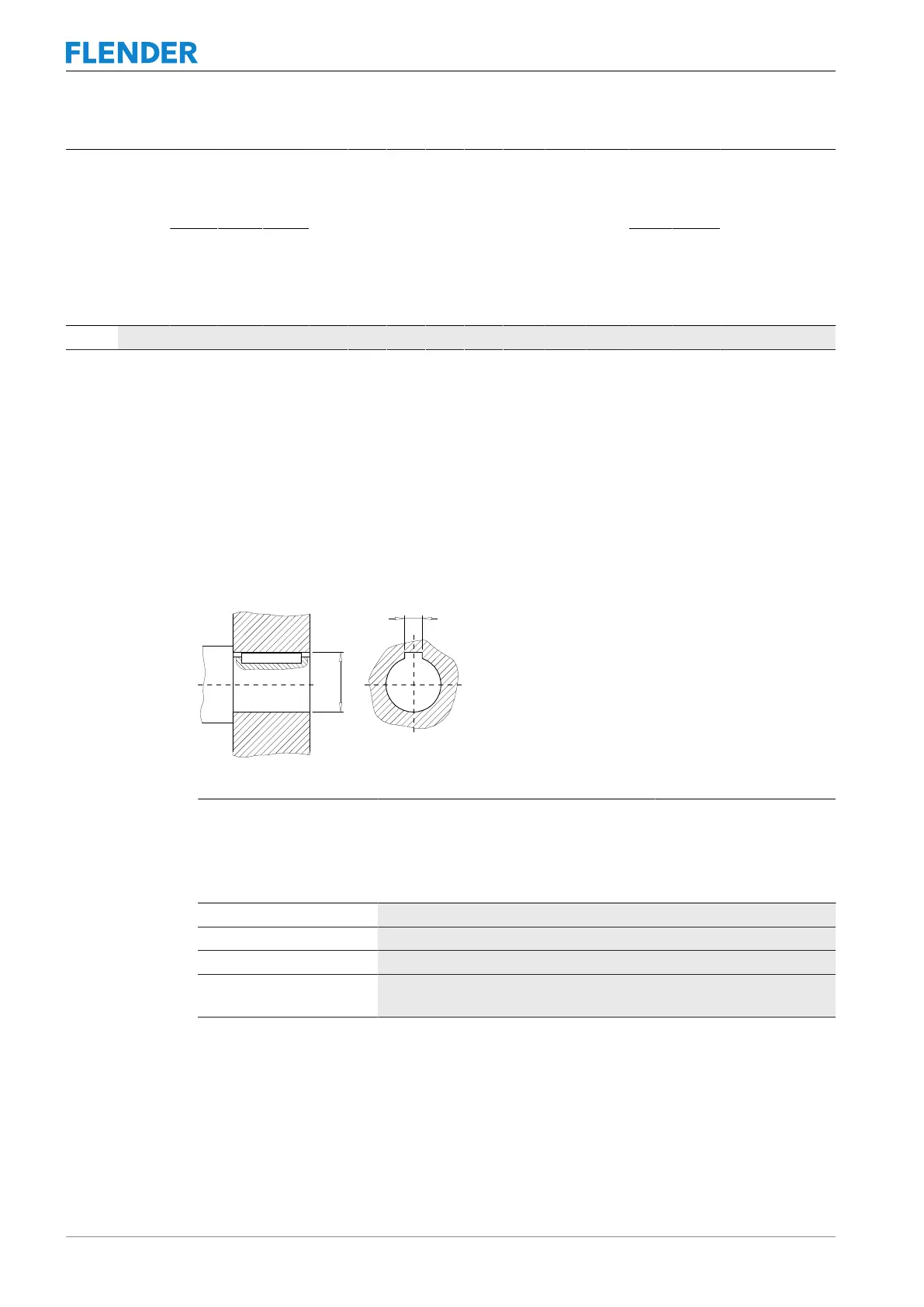
A.1.4 Flat groove in TAPER clamping bushes (101), (102) Speeds, geometry data and weights
FigureA-4:Flat groove in TAPER clamping bushes
TAPER-
Clamping bush
No.
Bore
D
mm
Width
B
JS9
mm
Hub groove depth
D + T2
mm
1008 24 8 D + 2
1008 25 8 D + 1.3
1108 28 8 D + 2
1610
1615
42 12 D + 2.2
TableA-4: Flat groove in TAPER clamping bushes
A.2 Shaft misalignment values during operation Shaft misalignment values during operation
The maximum permissible radial and angular misalignment depends on the operating speed.