Assembly
5.1 Preparatory work
28 Edition 09/2022 M3401-02en
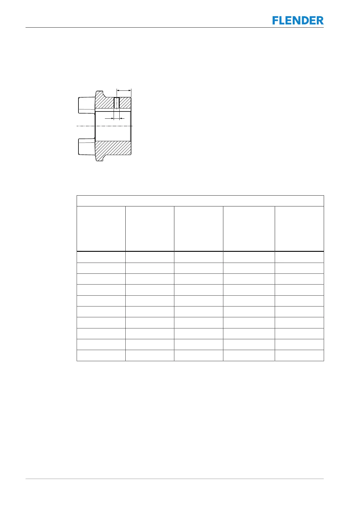
Diameter and axial position of the threaded hole in the hub
The following diagram shows the axial position of the threaded hole.
Figure5-2:Diameter and axial position of the threaded hole in the hub
The following table contains the values for the diameter and axial position of the threaded
hole depending on the coupling size.
Coupling part 1/2 (1 or 2) of types BWN and BNT
Coupling size Tapped hole
d1
Clearance
e
mm
Tightening torque
T
A
Nm
Width across
flats
Hexagon socket
wrench
mm
19 M5 10 3 2.5
24 M5 10 3 2.5
28 M8 15 8 4
38 M8 15 8 4
42 M8 20 8 4
48 M8 20 8 4
55 M10 20 15 5
65 M10 20 15 5
75 M10 25 15 5
90 M12 30 25 6
Table5-2: Tapped hole, tightening torque and width A/F
Apply the specified tightening torques as listed in Section Tightening procedure (Page62).
Position of the threaded hole with respect to the parallel keyway
The threaded hole for the set screw is positioned on the parallel keyway.