Assembly
5.3 Aligning the coupling
32 Edition 09/2022 M3401-02en
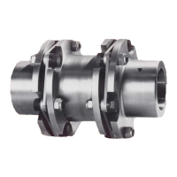
3. Line up the half blind holes of the TAPER clamping bush (101) or (102) with the half
tapped holes of the coupling part 3(3) or 4(4).
4. Apply a small quantity of liquid screw locking agent (e.g. Loctite 243 medium strength) to
the screws of the TAPER clamping bush.
5. Insert the screws for the TAPER clamping bush (101), (102) into the blind hole/tapped
hole combination and tighten them slightly.
Install the TAPER clamping bush (101), (102) from the shaft end face end in the case of
coupling part 3(3), and from the shaft shoulder end in the case of coupling part4(4).
6. Position the coupling part 3 (3) or 4 (4) together with the TAPER clamping bush (101) or
(102) on the shaft. When doing this the shaft must not protrude or be set back from the
inner side of the hub.
7. Gradually tighten the screws for the TAPER clamping bush (101), (102) in sequence up
to the specified tightening torque T
A
(see section Tightening torques and widths A/F
(Page62)).
As the screws are tightened, the hub is drawn against the TAPER clamping bush (101),
(102) and the bush thus pressed onto the shaft.
8. Fill any unused bores of the TAPER clamping bush (101), (102) with a suitable grease to
prevent the ingress of dirt.
9. After a brief period of operation under load, check the tightening torques T
A
again (see
section Tightening torques and widths A/F (Page62)). When liquid screw locking agent
is used (for use in potentially explosive atmospheres) the tightening torques do not have
to be checked.
5.3 Aligning the coupling5.3 Aligning the coupling
5.3.1 Purpose of alignment5.3 Aligning the coupling
The shafts that are joined by the coupling are never on an ideal precise axis but have a cer-
tain amount of misalignment.
Misalignment in the coupling leads to restoring forces that can stress adjacent machine parts
(e.g. the bearings) to an unacceptable extent.
The misalignment values in operation result from the following:
• Misalignment due to assembly
Incorrect position due to a lack of precision when aligning
• Misalignment due to operation
Example: Load-related deformation, thermal expansion
You can minimise misalignment by aligning after assembly. A lower misalignment in the
coupling has the following advantages:
• Reduced wear of the elastomer components
• Reduced restoring forces
• Misalignment reserves for operation of the coupling
You can find the maximum permitted shaft misalignment values during operation in section
Shaft misalignment values during operation (Page59).