Assembly
5.3 Aligning the coupling
M3401-02en Edition 09/2022 33
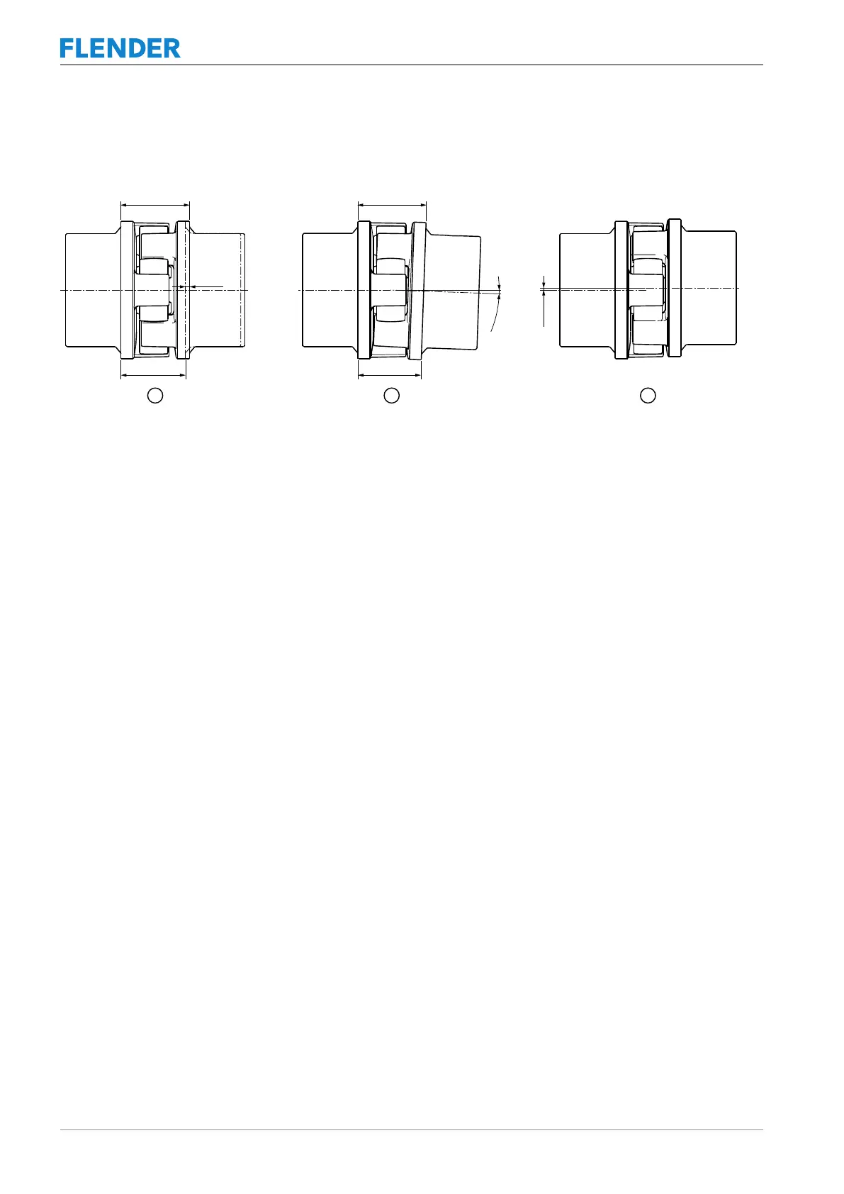
5.3.2 Possible misalignment5.3 Aligning the coupling
The following types of misalignment can occur:
6
PD[
6
PLQ
˂.D
˂.Z
˂.U
6
PD[
6
PLQ
Figure5-5:Possible misalignment
① Axial misalignment (ΔKa)
② Angular misalignment (ΔKw)
③ Radial misalignment (ΔKr)
5.3.2.1 Axial misalignment5.3 Aligning the coupling
Set the axial misalignment ΔKa to a value within the permissible tolerance range of dimen-
sion S2.
You can find the values for dimension S2 in section Speeds, geometry data and weights
(Page55).
5.3.2.2 Angular misalignment5.3 Aligning the coupling
Determine the value ΔS2 (ΔS2 = S2
max
- S2
min
). The determined value ΔS2 may not exceed
the value ΔS2
perm
.
You can find the values for ΔS2
perm
in section Shaft misalignment values during operation
(Page59).
If required, you can calculate the angular misalignment ΔKw as follows:
ΔKw [rad] = ΔS2 / DA
ΔKw [deg] = (ΔS2 / DA) · (180 / π)
If required, you can calculate the permissible angular misalignment ΔKw
perm
as follows:
ΔKw
perm
[rad] = ΔS2
perm
/ DA
ΔKw
perm
[deg] = (ΔS2
perm
/ DA) • (180 / π)
DA in mm see section Speeds, geometry data and weights (Page55)
ΔS2
perm
see section Shaft misalignment values during operation (Page59)
5.3.2.3 Radial misalignment5.3 Aligning the coupling
Determine the value ΔKr. The determined value ΔKr may not exceed the value ΔKr
perm
.