7 Connection
FLUXUS F501 7.1 Transducers
53
UMFLUXUS_F501V1-3EN, 2020-06-30
7.1.3 Connection of the transducer cable to the junction box
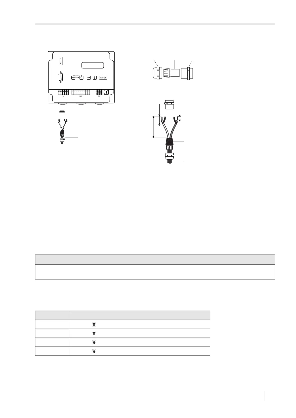
• Remove the blind plug for the connection of the transducer cable, see Fig. 7.5.
• Open the cable gland of the transducer cable. The compression part remains in the cap nut.
• Push the transducer cable through the cap nut and the compression part.
• Prepare the transducer cable.
• Shorten the external shield and brush it back over the compression part.
• Screw the gasket ring side of the basic part into the junction box.
• Insert the transducer cables into the junction box.
• Fix the cable gland by screwing the cap nut onto the basic part.
• Connect the transducer cable to the terminals of the junction box, see Fig. 7.5 and Tab. 7.3.
Fig. 7.4: Connection of the extension cable to the transmitter
1 – cap nut
2 – compression part
3 – basic part
4 – external shield brushed back
5 – extension cable
Notice!
For good electromagnetic compatibility (EMC), it is important to ensure good electrical contact between the external
shield and the cap nut (and thus the housing).
Tab. 7.3: Terminal assignment
terminal connection
V transducer (core)
VS transducer (internal shield)
RS transducer (inner shield)
R transducer (core)
cable gland
1 2 3
70 mm
20 mm
10 mm
4
5
5
 Loading...


