7 Connection
7.2 Power supply FLUXUS F501
2020-06-30, UMFLUXUS_F501V1-3EN
58
7 Connection
7.2 Power supply
• Connect the power cable to the transmitter.
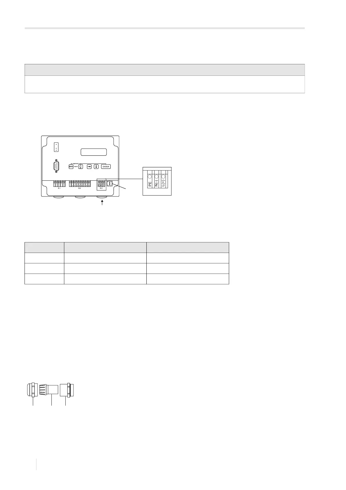
For the connection of the power supply cable to the transmitter, see section 7.2.1, Fig. 7.9 and Tab. 7.6.
7.2.1 Cable connection
• Remove the blind plug to connect the cable to the transmitter.
• Prepare the cable with an M20 cable gland.
• The used cable has to have a wire cross-section of 0.25…2.5 mm².
• Push the cable through the cap nut, compression part and basic part of the cable gland.
• Insert the cable into the housing of the transmitter.
• Screw the sealing ring side of the basic part into the transmitter housing.
• Fix the cable gland by screwing the cap nut onto the basic part.
• Connect the cable to the terminals of the transmitter.
Important!
The degree of protection of the transmitter will only be guaranteed if the power cable fits firmly and tightly in the cable
gland.
Fig. 7.9: Connection of the power supply to the transmitter
1 – fuse
2 – connection of the power supply
Tab. 7.6: Terminal assignment
terminal connection AC connection DC
PE earth earth
N(-) neutral -
L(+) phase +
Fig. 7.10: Cable gland
1 – cap nut
2 – compression part
3 – basic part
1
2
21 3
 Loading...


