7 Connection
FLUXUS F501 7.3 Outputs
59
UMFLUXUS_F501V1-3EN, 2020-06-30
7.3 Outputs
• Connect the output cable to the transmitter.
For the connection of the output cable to the transmitter, see section 7.2.1, Fig. 7.11 and Tab. 7.7.
Important!
The max. permissible voltage between the outputs and against PE is 60 V DC (permanent).
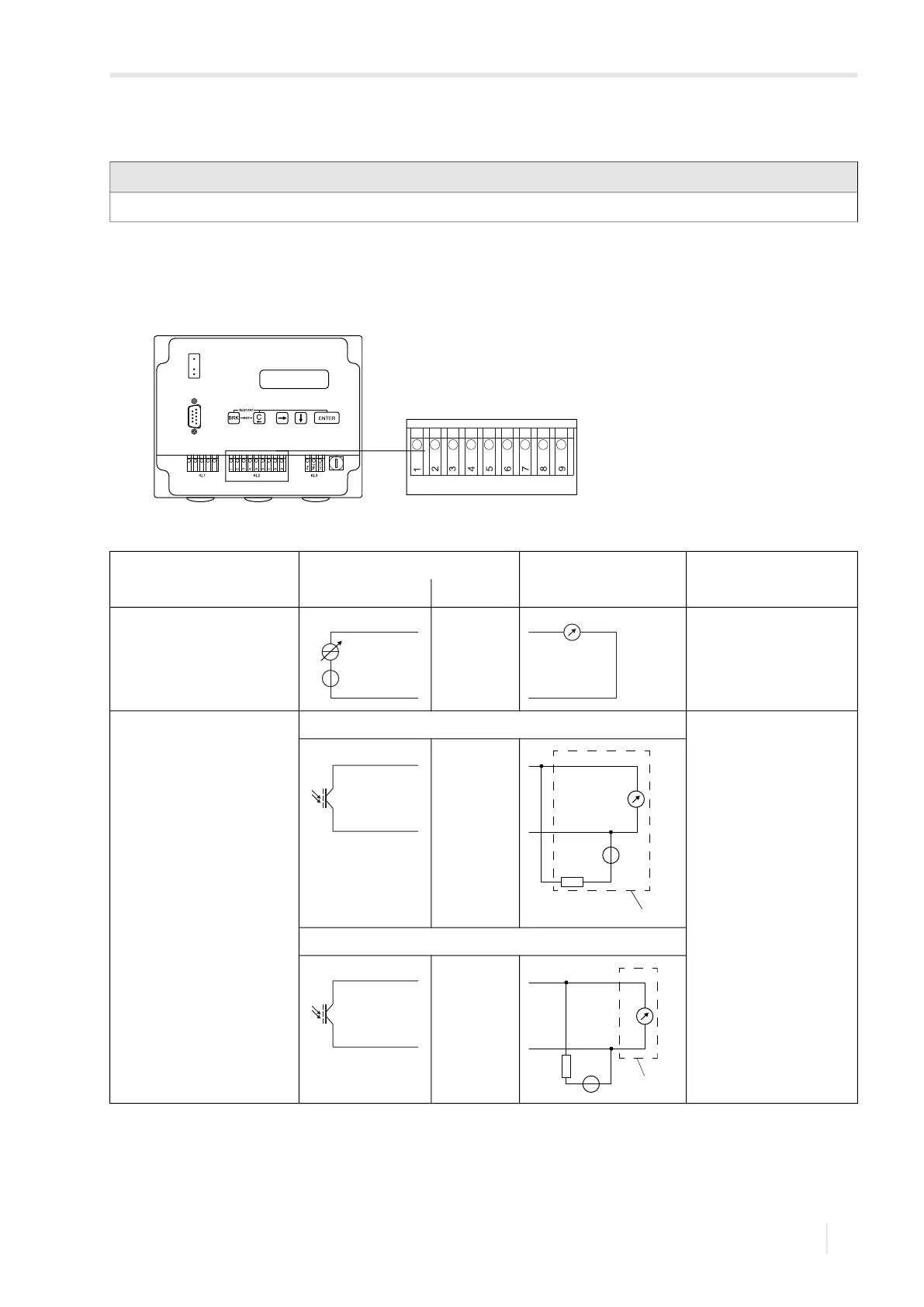
Fig. 7.11: Connection of the outputs on the transmitter
Tab. 7.7: Circuit of the outputs
output transmitter external circuit remark
internal circuit connection
active current output R
ext
< 500 Ω
binary output (optorelay) circuit 1 U
ext
≤ 28 V DC
I
c
≤ 100 mA
R
c
[kΩ] = U
ext
/I
c
[mA]
circuit 2
The number, type and the connections of the outputs depend on the order.
R
ext
is the sum of all ohmic resistances in the circuit (e.g., resistance of the conductors, resistance of the ammeter/voltmeter).
+
-
I1: 6
I1: 5
+
-
mA
B1/B2: 2/4
B1/B2: 1/3
R
c
V
U
ext
+
-
PLC
B1/B2: 2/4
B1/B2: 1/3
U
ext
R
c
V
+
PLC
-
 Loading...


