FLUXUS F70x 7 Connection
70 UMFLUXUS_F7V4-6-2EN, 2017-10-01
FLUXUS F705, F706
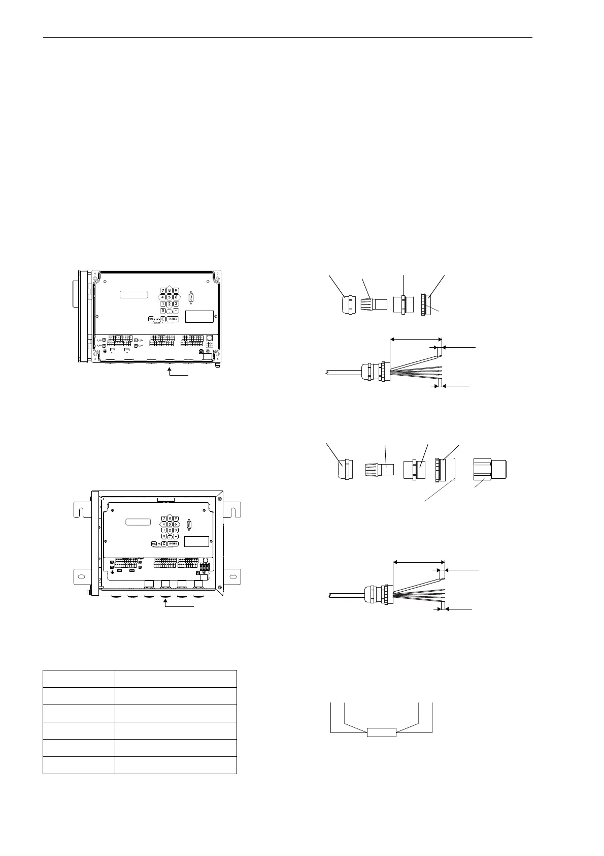
• Remove the second blind plug on the right for the connection of the temperature probe (see Fig. 7.27).
• Open the cable gland of the temperature probe. The compression part remains in the cap nut (see Fig. 7.28 and Tab.
7.12).
• Push the cable of the temperature probe through the cap nut, the compression part, the basic part, the reducer and the
sealing ring. (Sealing ring: only for cable gland M20, not for cable gland 1/2 NPS.)
• Prepare the cable.
• Insert the cable into the housing.
• Tightly screw the basic part into the reducer.
• Fix the cable gland by screwing the cap nut onto the basic part.
• Fix the transducer cable by tightening the cable gland with the ferrite nut.
• Connect the temperature probe to the terminals of the transmitter (see Fig. 7.2, Fig. 7.27 and Tab. 7.13).
Fig. 7.25: Transmitter FLUXUS F704 Fig. 7.26: Cable gland and preparation
Fig. 7.27: Transmitter FLUXUS F705, F706
(example with FLUXUS F705)
Fig. 7.28: Cable gland and preparation
Tab. 7.13: Terminal assignment of the transmitter
terminal temperature probe
Fig. 7.29: Temperature probe
T1a...T4a red
T1A...T4A red/blue
T1b...T4b white/blue
T1B...T4B white
S1...S4 shield
AVSAV
AGN
ARS
AR
BVSBV
BGN
BRS
BR
SA1
SA2
SA3
SA4
SB1
SB2
SB3
SB4
T1a
T1b
S2 T2a
T3a
T3b
S4
T4a
T2b
T4b
T1A
T1B
S1 T2A
T3A
T3B
S3
T4A
T2B
T4B
A+
B-
P1+ P2+
P4+
P5a
P6a P7a
P3+
101
103
P1- P2-
P4-
P5b
P6b
P7b
P3-
PE
N(-)
L(+)
cap nut
compression
part
basic part reducer
gasket ring side
AVS
AV
AGN
ARS
X2
X_BV
X_BR
X_AV
X_AR
X1
AR
BVS
BV
BGN BRS
BR
SA1 SA2 SA3 SA4 SB1
SB2
SB3
SB4
T1a T1b
S2 T2a
T3a
T3b
S4
T4a
T2b
T4b
T1A T1B
S1 T2A
T3A
T3B
S3
T4A
T2B
T4B
A+
B-
P1+ P2+
P4+
P5a
P6a P7a
P3+
101
103
P1- P2-
P4-
P5b
P6b
P7b
P3-
PE
N(-)
L(+)
cap nut
compression
part
basic part
reducer
ferrite nut
sealing ring:
only for cable gland M20,
not for cable gland 1/2 NPS
redred/blue white/blue white
 Loading...


