7 Connection
7.1 Transducers FLUXUS G809
2020-06-25, UMFLUXUS_G809V2-2EN
64
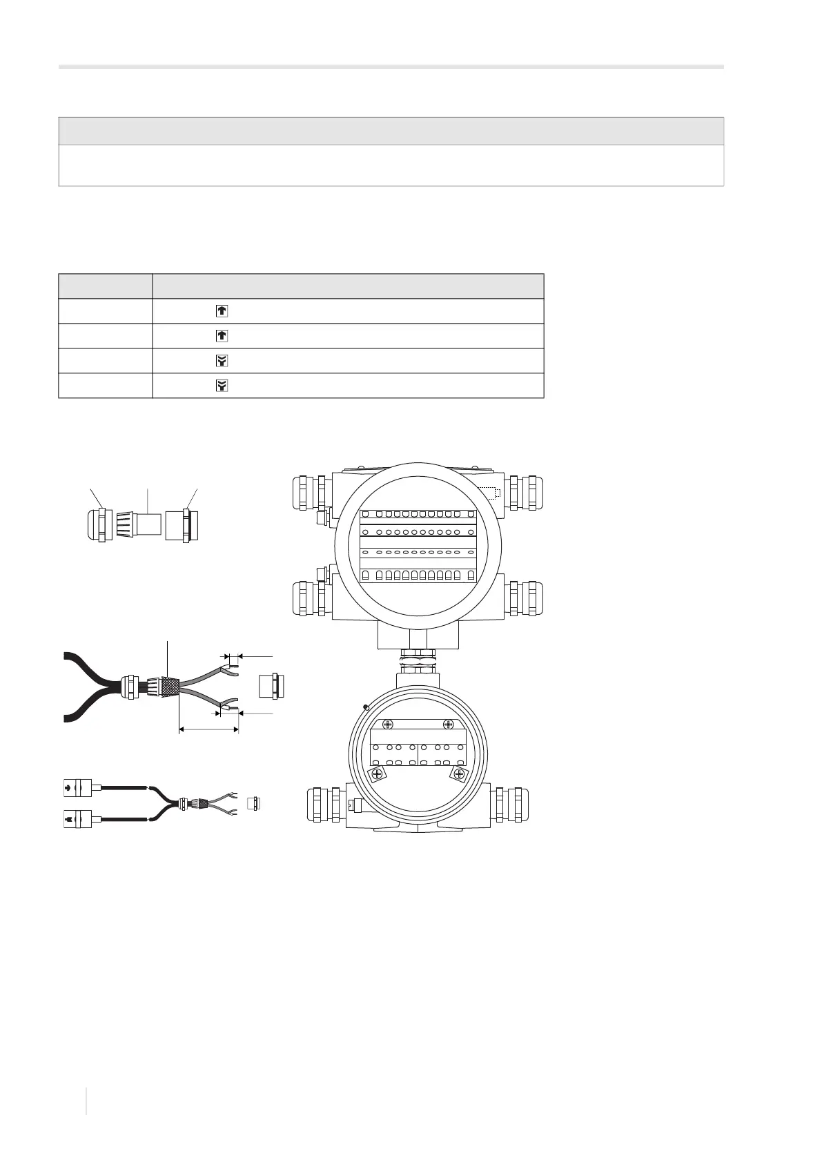
• Fix the cable gland by screwing the cap nut onto the basic part.
• Connect the transducer cable to the terminals of the transmitter, see Fig. 7.3 and Tab. 7.1.
7.1.1.2 Transducer cable with stainless steel conduit and stripped cable ends
• Remove the blind plug for the connection of the transducer cable.
• Insert the transducer cable into the housing.
• Fix the transducer cable by tightening the cable gland.
• Connect the transducer cable to the terminals of the transmitter, see Fig. 7.4 and Tab. 7.2.
Notice!
For good electromagnetic compatibility (EMC), it is important to ensure good electrical contact between the external
shield and the cap nut (and thus the housing).
Tab. 7.1: Terminal assignment
terminal connection
AV transducer (core)
AVS transducer (internal shield)
ARS transducer (inner shield)
AR transducer (core)
Fig. 7.3: Connection of the transducer cable with plastic cable jacket and stripped cable ends to
the transmitter
1 – cap nut
2 – compression part
3 – basic part
4 – external shield brushed back
cable gland
1 2 3
70 mm
20 mm
10 mm
4
AR
L
(+)
N
(-)
PE
ARS AVAVS BR BRS BVBVS