3 General principles
3.4 Undisturbed flow profile FLUXUS H721
2022-05-15, UMFLUXUS_H721V1-5EN
18
Free inlet or outlet pipe section
Select the measuring point at a pipe section where the pipe cannot run empty.
3.4 Undisturbed flow profile
Some flow elements (e.g., elbows, valves, pumps, reducers) distort the flow profile in their vicinity. The axisymmetrical
flow profile in the pipe needed for correct measurement is no longer given. A careful selection of the measuring point helps
to reduce the impact of disturbances.
It is most important that the measuring point is chosen at a sufficient distance from any disturbances. Only then it can be
assumed that the flow profile in the pipe is fully developed. The use of the disturbance correction (see section 13.2.4)
allows a measurement even at smaller distances of min. 2 D.
The recommended straight inlet and outlet pipe lengths for different types of flow disturbances are shown in the following
table.
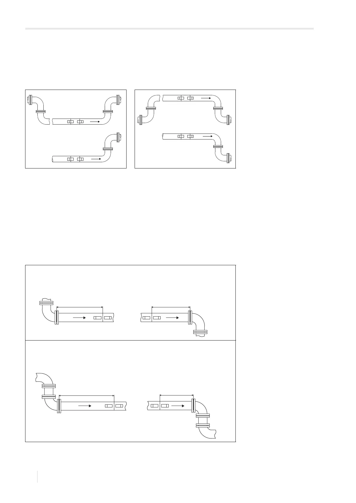
Fig. 3.14: Recommended transducer
mounting position
Fig. 3.15: Disadvantageous transducer
mounting position
Tab. 3.3: Recommended distance from disturbances
D – nominal pipe diameter at the measuring point
l – recommended distance between disturbance and transducer position
disturbance: 90° elbow
inlet: l ≥ 10 D
(l ≥ 2 D with disturbance correction)
outlet: l ≥ 3D
disturbance: double elbow
inlet: l ≥ 10 D
(l ≥ 2 D with disturbance correction)
outlet: l ≥ 3D