6 Mounting
FLUXUS H721 6.2 Transducers
59
UMFLUXUS_H721V1-5EN, 2022-05-15
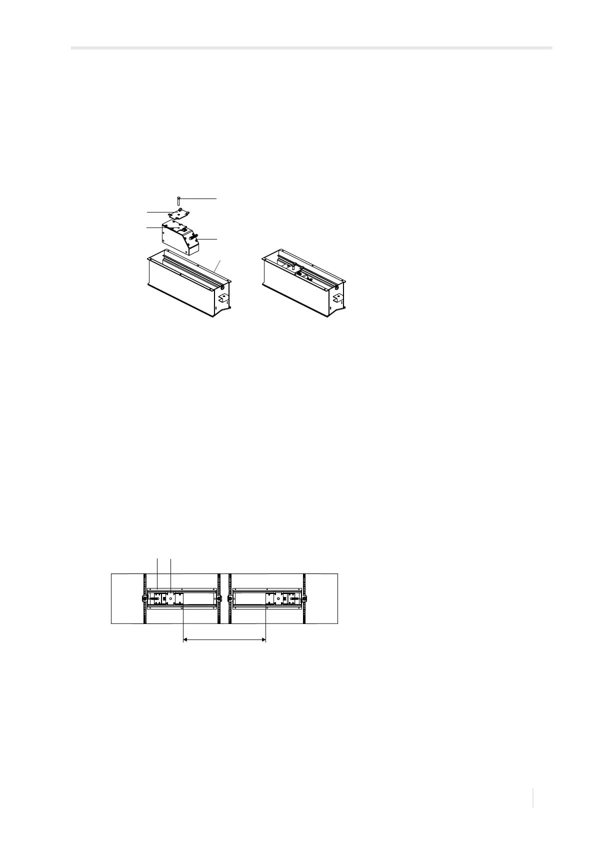
Step 3: Mounting of the transducers in the mounting fixture PermaLok
• Stick coupling foil (or apply some coupling compound for a short-term installation) on the contact surface of the
transducer. The coupling foil can be fixed to the contact surface with a small amount of coupling compound.
• Insert the transducer into the rail.
• Position the slider on the transducer. The screw of the slider has to fit into the dugout on the top of the transducer, see
Fig. 6.31.
• Repeat the steps for the second transducer.
• Position the transducers on the rail in such a way that the engravings on them form an arrow. The transducer cables
show in opposite directions.
• Adjust the transducer distance displayed by the transmitter (see Fig. 6.66).
• Tighten the screw of the slider until the transducers are firmly pressed to the pipe surface.
• Measure once again the transducer distance. Correct it, if necessary.
• Pass the transducer cables through the cable bushing to protect them from mechanical strain.
• Check the transducer distance as described in section 9.4.
• Check transmitter for signal, then put the cover on the rail.
• Tighten the screws of the cover.
Fig. 6.65: Installation of the transducers
1–rail
2 – transducer
3 – dugout
4 – slider
5 – screw of the slider
Fig. 6.66: Adjustment of the transducer distance
1–rail
2 – slider
a – transducer distance