FLIRCM85USERMANUALDocumentIdentifier:CM85‐en‐US_AB
24
5.11ContinuityTest
Warning: Do not do diode, resistance or continuity tests before you have removed the power from
capacitors and other devices under test during a measurement. Injury to persons can occur.
1.
Setthefunctionswitchtothe position.
2.
InserttheblackprobeleadintothenegativeCOMterminalandtheredprobeleadinto
thepositiveΩterminal.
3.
UsetheMODEbuttontoselectcontinuitymeasurement.The indicatorwillbe
displayed.
4.
Touchthetipsoftheprobeacrossthecircuitorcomponentundertest.
5.
Iftheresistanceislessthan30Ω,themeterwillbeep.
5.12DiodeTest
Warning:Donotperformdiode,resistanceorcontinuitytestsbeforeremovingthepowerfrom
capacitorsandotherdevicesundertestduringameasurement.Injurytopersonscanoccur.
1. Setthefunctionswitchtothediode
position.
2. InserttheblackprobeleadintothenegativeCOMterminalandtheredprobeleadinto
thepositiveΩterminal.
3. UsetheMODEbuttontoselectthediodetestfunction.Thediodeindicator
willbe
displayed.
4. Touchthetipsoftheprobeacrossthediodeorsemiconductorjunctionundertest.
5. Ifthereadingisbetween±0.40and+0.80V,thecomponentisgood;bADorO.Ldisplays
indicateadefectivecomponent.
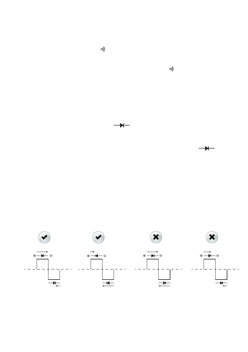
ThisFLIRmeterchecksdiodesusinganalternatingtestsignalsent
throughthediodeinboth
directions.Thisallowstheusertocheckthediodewithouthavingtoreversepolaritymanually.
Themeterdisplaywillshow±0.4~0.7Vforagooddiode,bAdforashorteddiode,andO.Lfor
anopeneddiode.SeeFig.5.7below:
Figure5.7
DiodeTests
- 0.4V
O.LbAd + 0.4V