Rue J.H. Cool 19a | B-4840 Welkenraedt | BELGIUM
Tel. : +32 (0)87 899 799 | Fax : +32 (0)87 899 790
E-mail : info@flow-tronic.com | www.flow-tronic.com
- 20 -
4 Operation
The IFQ Monitor does not connect to any laptop or computer. All changes in settings are made with the navigation
keys (Figure 1 on page - 7 -).
The site and velocity sensor configuration are made using RTQ-Log software and connecting the sensor directly to
the computer.
4.1 Configuration of velocity sensor
1.1.1 Configuration with RTQ-Log for IFQ MONITOR or PLC
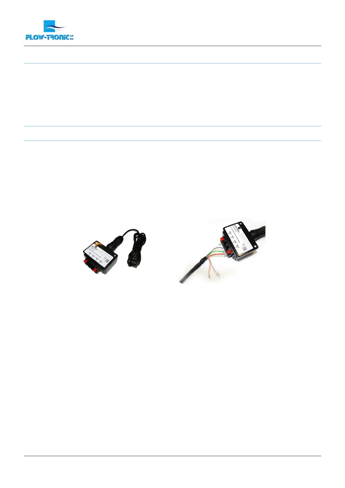
Use the RAV-4001 communication cable to connect sensors equipped with open end cables to a computer. The
adaptor from the RAV-4001 diposes of 4 quick connect terminals.
1. Connect the black and white cables from the sensor to the terminal of the RAV-4001.
2. Connect the red and green cables from the sensor to the terminal of the RAV-4001.
3. Connect the USB connector from the RAV-4001 to the computer and launch RTQ-Log.
Note: When connected via USB communication cable (RAV-4001), the sensor does not need to be
connected to a separate power supply as the power coming from the computer is sufficient.
Figure 12: RAV-4001 USB communication cable for open end cables
Refer to the setup & operation manual from the velocity sensor for further information.
 Loading...