Rue J.H. Cool 19a | B-4840 Welkenraedt | BELGIUM
Tel. : +32 (0)87 899 799 | Fax : +32 (0)87 899 790
E-mail : info@flow-tronic.com | www.flow-tronic.com
- 17 -
3.2.3.4 Contact output connections
Important Note: The maximum current allowed through the contact is 6A.
1. Disconnect power from the IFQ Monitor.
2. Screw off the cover attachement screws (Figure 1 on page - 7 -) in order to access the connection
chamber.
3. Insert the cable(s) through the cable glands (Figure 1 on page - 7 -).
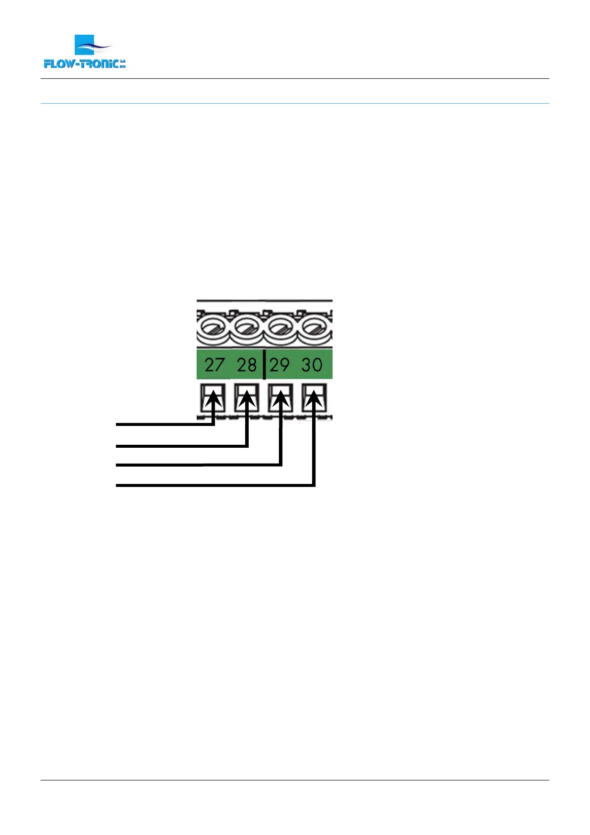
4. Install each wire into the terminal block (Figure 10)
Note: The alarm is Normaly Closed (NC). It means that the contact is closed (terminal N° 27 is linked to
connection 28) when the device is not supplied.
5. Tighten each wire and then tug gently to make sure the connection is tight.
6. Tighten the cable gland(s) where the cable(s) go(es) through.
7. Install the connection chamber cover and screw the cover attachement screws back in.
Figure 10: Connections for contact output
 Loading...