Rue J.H. Cool 19a | B-4840 Welkenraedt | BELGIUM
Tel. : +32 (0)87 899 799 | Fax : +32 (0)87 899 790
E-mail : info@flow-tronic.com | www.flow-tronic.com
- 15 -
3.2.3.2 ULS (or other level sensor) cable connections
1. Disconnect power to the IFQ Monitor.
2. Screw off the cover attachement screws (Figure 1 on page - 7 -) in order to access the connection
chamber.
3. Insert the cable(s) through the cable gland (Figure 1 on page - 7 -).
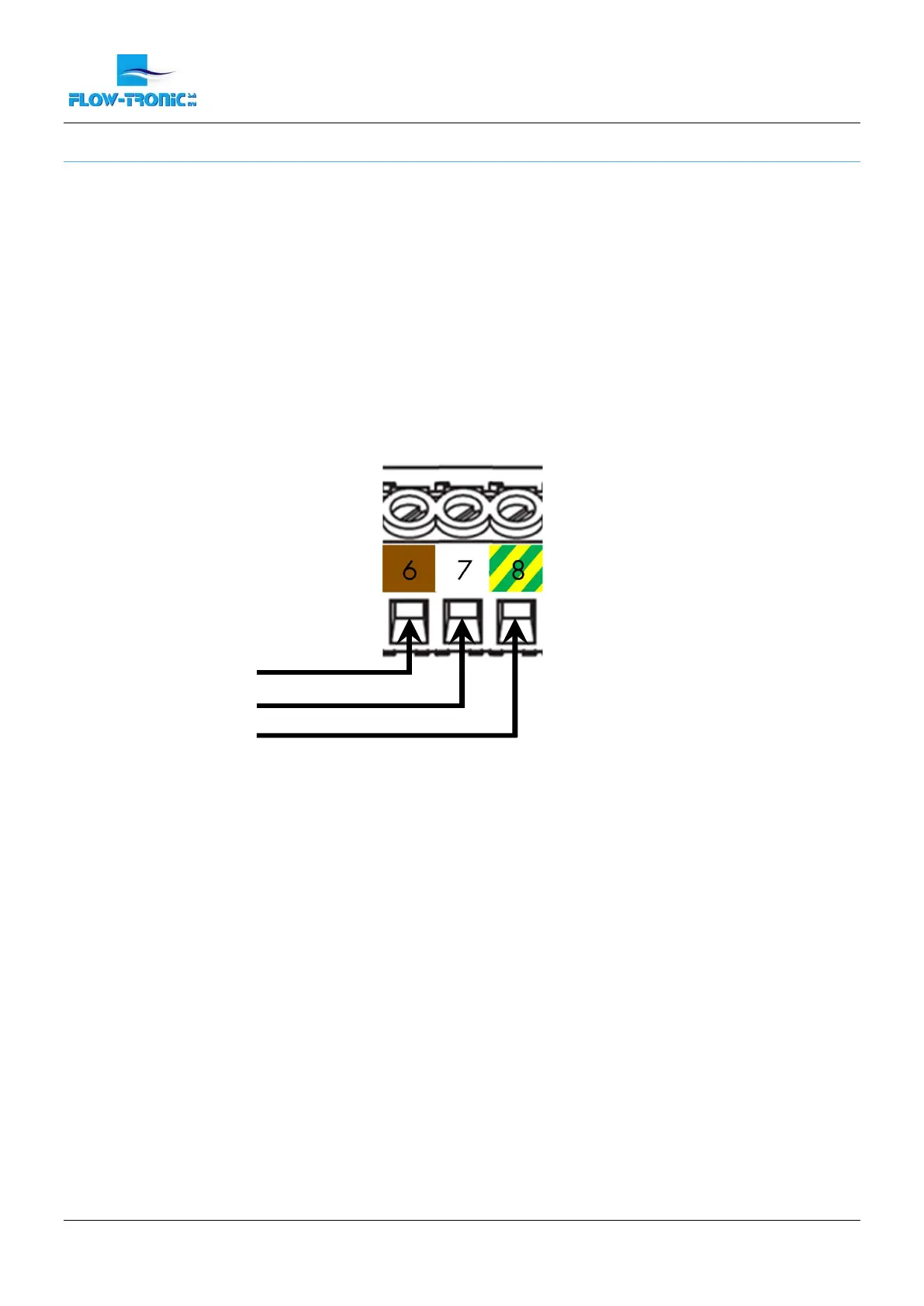
4. Install each wire into the terminal block (Figure 8) :
a. If available connect the ground cable in terminal N° 8.
b. Connect the brown cable in terminal N° 6 and the white cable in terminal N° 7.
5. Tighten each wire and then tug gently to make sure the connection is tight.
6. Tighten the cable gland where the cable goes through.
7. Install the connection chamber cover and screw the cover attachement screws back in.
Figure 8: Connections for ULS-02, ULS-06 or other level sensor
 Loading...