Rue J.H. Cool 19a | B-4840 Welkenraedt | BELGIUM
Tel. : +32 (0)87 899 799 | Fax : +32 (0)87 899 790
E-mail : info@flow-tronic.com | www.flow-tronic.com
- 16 -
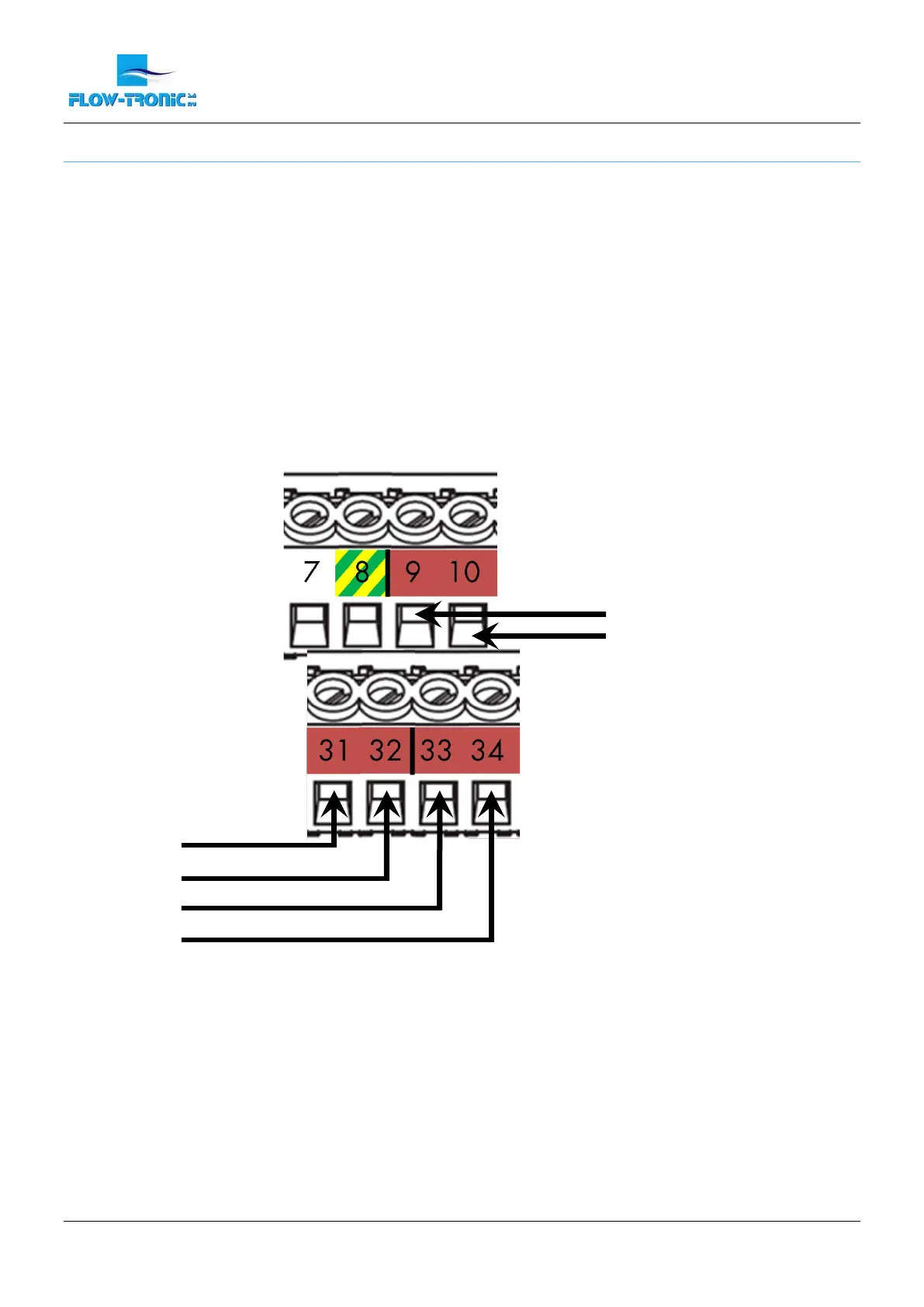
3.2.3.3 4-20 mA output connections
Important Note: The maximum load is 250Ω.
1. Disconnect power to the IFQ Monitor.
2. Screw off the cover attachement screws (Figure 1 on page - 7 -) in order to access the connection
chamber.
3. Insert the cable(s) through the cable glands (Figure 1 on page - 7 -).
4. Install each wire into the terminal block as shown in Figure 9.
Note: Each terminal is labeled (+, -) for polarity. This is the voltage polarity when a load resistance is placed
across the terminals.
5. Tighten each wire and then tug gently to make sure the connection is tight.
6. Tighten the cable gland(s) where the cable(s) go(es) through.
7. Install the connection chamber cover and screw the cover attachement screws back in.
Figure 9: Connections for 4-20 mA outputs
 Loading...