Rue J.H. Cool 19a | B-4840 Welkenraedt | BELGIUM
Tel. : +32 (0)87 899 799 | Fax : +32 (0)87 899 790
E-mail : info@flow-tronic.com | www.flow-tronic.com
- 29 -
5.2.2 Probe Type Menu
5.2.2.1 ULS-02 & ULS-06
These 2 sensor configurations (ULS-02 & ULS-06) are implemented in the IFQ Monitor.
Chose the appropriate sensor: ULS-02 or ULS-06 and press
Enter the probe offset using the arrows , , & then press. The range of the probe is
automatically computed with this information.
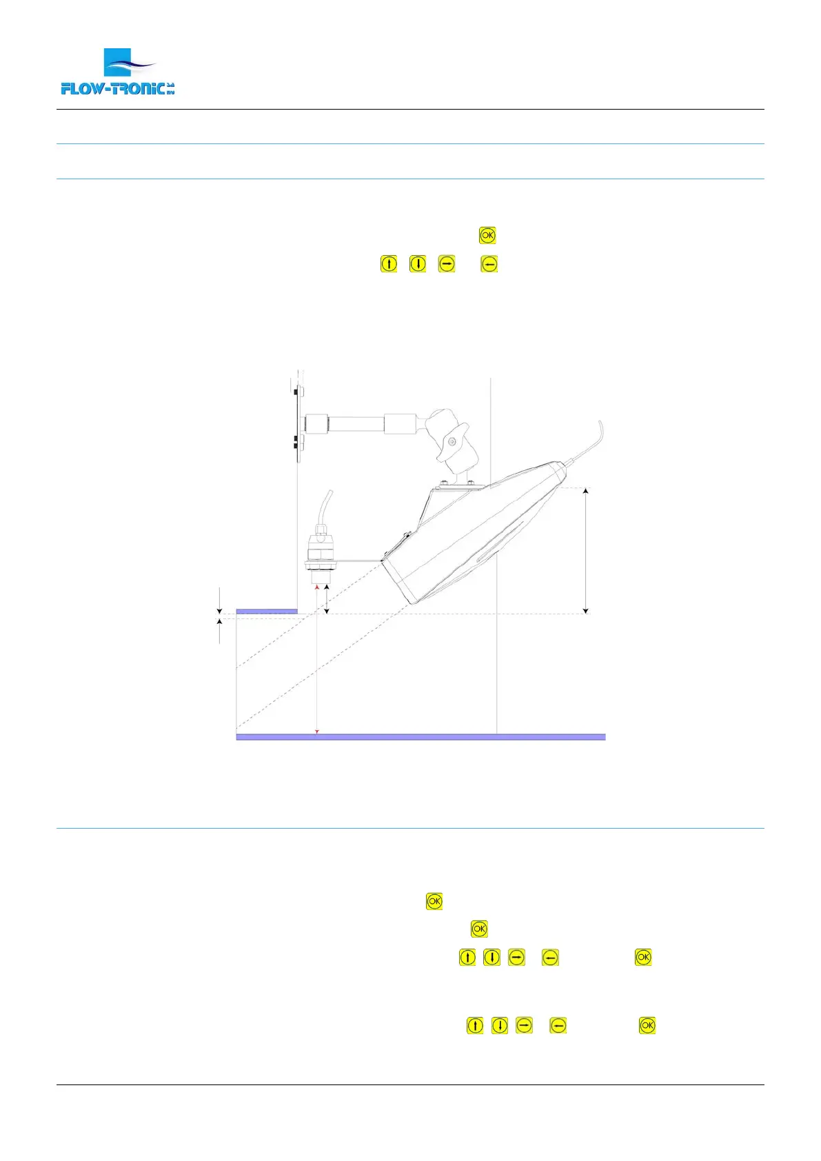
Note: The probe offset is the distance between the tip of the ULS-02 or ULS-06 sensor and the
bottom of the channel under the probe. Please refer to Figure 19.
Figure 19: ULS-02 & ULS-06 offset with a RAVEN-EYE
®
.
5.2.2.2 Other Probe
For any level sensor other than the sensors mentioned above (ULS-02 & ULS-06), please refer to the
manufacturer’s manual for setup. For implementing the values for an external level sensor, make the following:
1. Select “Probe Type “ in the “Main Menu” then press
2. Select “Other Probe” in the “Probe Type Menu”, then press
3. Enter the water level for the 4 mA value using the arrows , , & , then press
Note: The entered value can be positive or negative. This may depend on the offset or type of
probe used.
4. Enter the water level for the 20 mA value using the arrows , , & then press
Note: The entered value can be positive or negative. This may depend on the offset or type of
probe used.
 Loading...