Rue J.H. Cool 19a | B-4840 Welkenraedt | BELGIUM
Tel. : +32 (0)87 899 799 | Fax : +32 (0)87 899 790
E-mail : info@flow-tronic.com | www.flow-tronic.com
- 12 -
3.2.2.2 DC power
1. Remove the bottom cover (Figure 1 on page - 7 -).
2. Insert the power cable through the cable gland in the bottom of the enclosure.
3. Properly prepare each wire (
4. Figure 3 on page - 11 -).
5. Install the ground wire or cable braid to the protective earth terminal. Tighten the wire and then tug gently
to make sure the connection is tight. Refer to
6. Table 2 below for wiring.
7. Install the negative wire (black or blue) first and then the positive (red) wire into the power terminal.
Tighten each wire and then tug gently to make sure the connection is tight. Refer to
8. Table 2 below for wiring.
9. Tighten the cable gland to secure the cord.
10. Seal any unused openings in the enclosure with cable gland plugs.
11. Install the bottom cover.
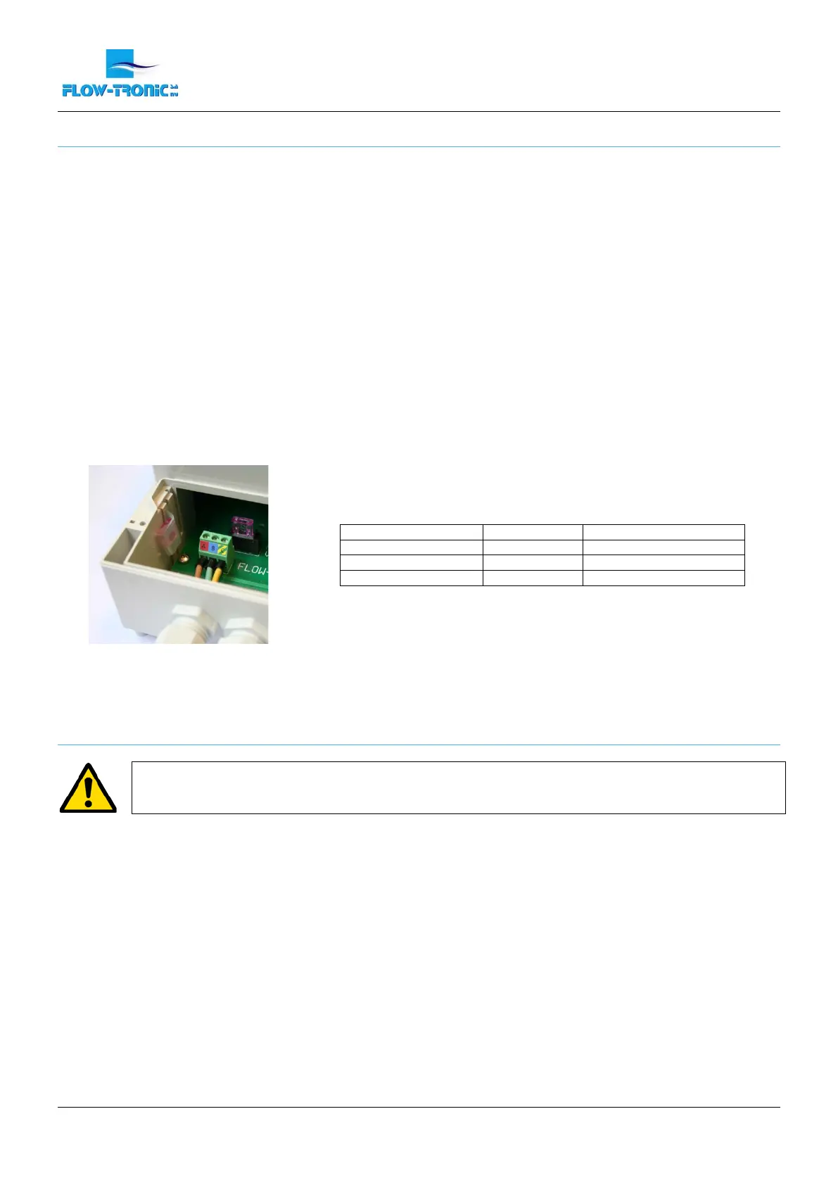
Figure 5: DC power wiring
Table 2: DC Wiring information
3.2.3 Wiring
DANGER
Potential confined space hazards. If conduit is installed from the IFQ Monitor to the sensor, the conduit
must be sealed to keep sewer gases out of the electronics.
The connection chamber is used for the RAVEN-EYE
®
or BELUGA
TM
, other sensors connections and all connections
from the IFQ Monitor to other systems (digital outputs & analog outputs).
Procedure
1. Disconnect power to the IFQ Monitor.
2. Screw off the cover attachement screws (Figure 1 on page - 7 -) in order to access the connection
chamber.
3. Insert the cable(s) through the cable glands (Figure 1 on page - 7 -).
4. Install each wire into the terminal block (Figure 6 on page - 13 -) using Table 3 on page - 13 - and as a
reference for cable connections. Tighten each wire and then tug gently to make sure the connection is
tight.
5. Tighten the cable gland where the cable(s) go through.
6. Install the connection chamber cover and screw the cover attachement screws back in.
 Loading...