Rue J.H. Cool 19a | B-4840 Welkenraedt | BELGIUM
Tel. : +32 (0)87 899 799 | Fax : +32 (0)87 899 790
E-mail : info@flow-tronic.com | www.flow-tronic.com
- 13 -
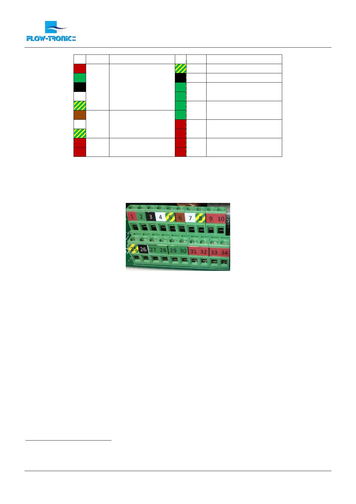
Table 3: Wiring map
Note: Each terminal is labeled (+, -) for polarity. This is the voltage polarity when a load resistance is placed across
the terminals.
Figure 6: Connection chamber
1
GDN = Ground
2
C = Common Terminal
3
NC = Normally Closed
4
NO = Normally Open
Purpose
Purpose
1
V+
RAVEN-EYE
25
GND
1
2
V-
26
0 V
3
RS485-
27
C
2
Contact Output:
Alarm
4
RS485+
28
NC
3
5
GND
1
29
C
2
Contact Output:
Totalizer
6
+
ULS-02, ULS-06
or other
level sensor
30
NO
4
7
-
31
+
Analogic Output:
Velocity
8
GND
1
32
-
9
+
Analogic Output:
Level
33
+
Analogic Output:
Flow
10
-
34
-
 Loading...