Rue J.H. Cool 19a | B-4840 Welkenraedt | BELGIUM
Tel. : +32 (0)87 899 799 | Fax : +32 (0)87 899 790
E-mail : info@flow-tronic.com | www.flow-tronic.com
- 18 -
3.2.3.5 Modbus RTU output cable connections
1. Disconnect power to the IFQ Monitor.
2. Screw off the cover attachement screws (Figure 1 on page - 7 -) in order to access the connection
chamber.
3. Insert the cable(s) through the cable gland (Figure 1 on page - 7 -).
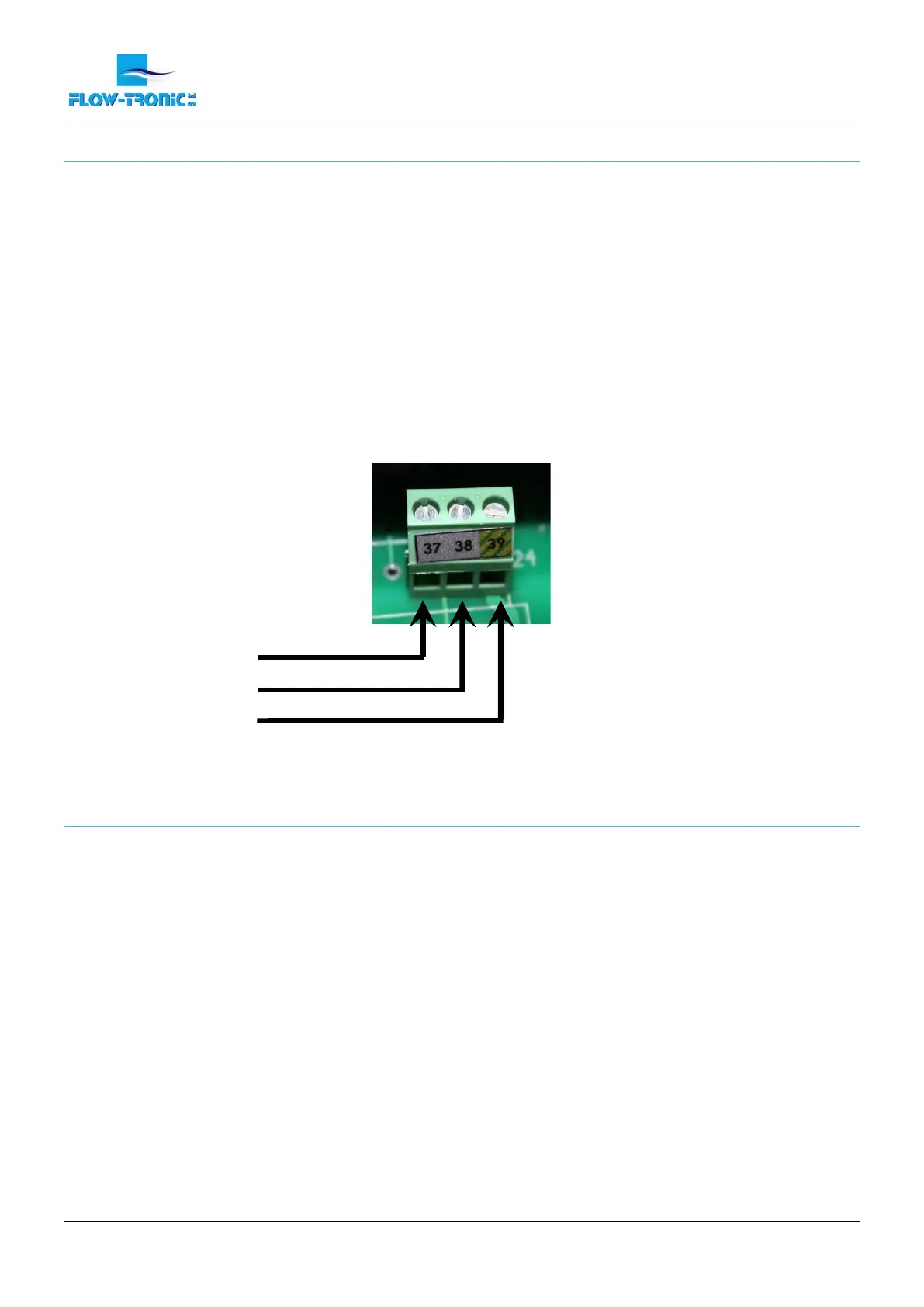
4. Install each wire into the terminal block (Figure 11) :
a. If available connect the ground cable in terminal N° 39.
b. Connect the RS485- in terminal N° 37 and the RS485+ in terminal N° 38.
5. Tighten each wire and then tug gently to make sure the connection is tight.
6. Tighten the cable gland where the cable goes through.
7. Install the connection chamber cover and screw the cover attachement screws back in.
Figure 11: Connections for Modbus RTU (slave) output
3.2.3.6 Modbus RTU output parameters
The IFQ Monitor is the slave device.
The serial communication has the following characteristics:
Communication (COM PORT): RS485
Protocol: MODBUS RTU
Baud rate: 19200 bauds
Number of bits: 8
Parity: None
Number of stop bits: 1
The IFQ Monitor uses the following MODBUS functions:
03 “Read holding registers”
Used data types:
Signed16 16 Bit signed integer
Unsigned16 16 Bit unsigned integer
Float32 32 Bit Floating Point
Word Order HI-LO = Hi Byte on lower register address
 Loading...