Fluke 190-104/190-204
Service Information
4-16
ADC
B
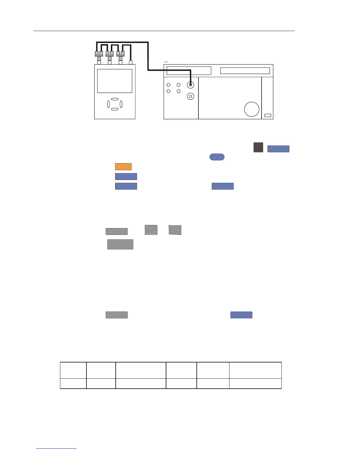
NORMAL SCOPE
FLUKE 5500A CALIBRATOR
PM9091
CONNECT TO CHANNEL A, B, C, D IN PARALLEL
50 OHM TERMINATIONNO
PM9093
PM9092
Figure 4-5. 5500A Scope Output to Test Tool Input A, B, C, D
2. Select the following Test Tool setup:
• Recall the created setup (e.g. SETUP 1, see section 4.4.3): press
SAVE
,
F2
RECALL , select SCREEN+SETUP 1 , press
ENTER
to recall the setup .
• Press
SCOPE
• Press
F1
– READINGS ON.
• Press
F2
– READING ... and select with
F1
– READINGS and with
the arrow keys:
Reading 1, on A, Hz,
Reading 2, on B, Hz,
Reading 3, on C, Hz,
Reading 4, on D, Hz.
3. Press
RANGE
select range 50 mV/div for A.
4. Using
TIMEsns
select the required time base setting.
5. Set the 5500A to source a sine wave according to the first test point in Table 4-6.
As no 50Ω termination is applied, the 5500 leveled sine wave output amplitude will
be twice the set value.
6. Observe reading
A and check to see if it is within the range shown under the
appropriate column.
7. Continue through the test points.
8. Next check channel B, C or D in succession:
Press
TRIGGER
and select B, C or D as trigger source with
F1
,
Press B, C or D to assign vertical ‘range’ and ‘move’ to channel B, C or D,
Observe reading B, C or D
9. When you are finished, set the 5500A to 0 (zero) Volt, and to Standby.
Table 4-6. Input A, B, C, D Frequency Measurement Accuracy Test
Model Time
base
5500A-SC... MODE Voltage Frequency Input A&B Reading
all 20 ms/div wavegen, sine 600 mVpp 16 Hz 15.90 to 16.10
 Loading...


