Fluke 43B
Applications Manual
64
5 Press SETUP
6 INPUT [2]
7 INPUT [2] COUPLING
8
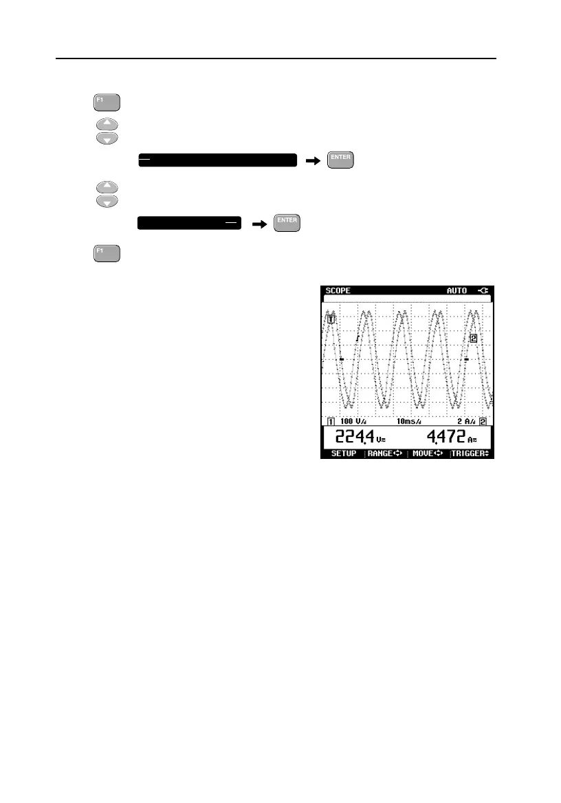
Press BACK. Two inputs are displayed simultaneously now
The ground marker icons (-) of both
waveforms are in the vertical mid of the
screen so that the waveforms cover each
other.
The trace identifiers [1] and [2] indicate the
relation between waveform and input signals.
In the next steps it is explained how to adapt
amplitude and vertical position of both
waveforms so that they do not cover each
other.
Use RANGE to adjust waveform amplitudes to 2 .. 4 divisions each. Use MOVE
to position one waveform in the upper half of the screen and the other
waveform in the lower half.
Fluke 43B now displays voltage and current and the display is continuously
refreshed: it always represents the present situation. This is the NORMAL mode
of the time base. You can press HOLD / RUN to freeze the display. SINGLE
mode can be used to capture events that occur only once.
COUPLING: OFF
DC

 Loading...


