Scope Mode
Triggering
5
61
Triggering
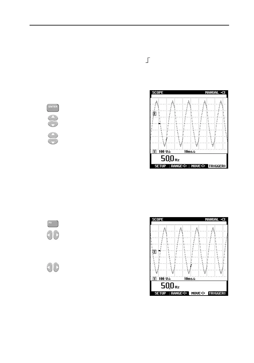
On the waveform you can see the trigger icon . This symbol represents the
level at which the waveform is triggered. Fluke 43B automatically selects the
most optimal level. If required, you can shift the trigger level to any desired
value.
1 Press TRIGGER
2 Press the upper button to
increase the trigger level
3 Press the lower button to
decrease the trigger level
Note that the Fluke 43B is capable of capturing signal details occurring prior to
the trigger point. This is a feature that is not offered in analog scopes. The
default is to display 2 divisions prior to the trigger point. This can be adjusted
between 0 and 10 divisions.
1 Press MOVE
2 Press the right button to
increase the number of
divisions before the trigger
point
3 Press the left button to
decrease the number of
divisions
The indication 1/2 AUTO in the header of the SCOPE screen changes to
MANUAL if waveform amplitude, number of periods, and triggering are all
under manual control.

 Loading...


