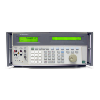
5500A
Getting Started
4
Operation Overview
The 5500A Calibrator may be operated at the front panel in the local mode, or remotely
using RS-232 or IEEE-488 ports. For remote operations, several software options are
available to integrate 5500A operation into a wide variety of calibration requirements.
Local Operation
Typical local operations include front panel connections to the Unit Under Test (UUT),
and then manual keystroke entries at the front panel to place the calibrator in the desired
output mode. The front panel layout facilitates hand movements from left to right, and
multiply and divide keys make it easy to step up or down at the press of a single key.
You can also review 5500A Calibrator specifications at the push of a button [available,
July, 1995]. The backlit liquid crystal display is easy to read from many different
viewing angles and lighting conditions, and the large, easy-to-read keys are color-coded
and provide tactile feedback when they are pressed.
Remote Operation (RS-232)
There are two rear-panel serial data RS-232 ports: SERIAL 1 FROM HOST, and
SERIAL 2 TO UUT (Figure 2). Each port is dedicated to serial data communications for
operating and controlling the 5500A during calibration procedures. For complete
information on remote operations, see Chapter 5.
The SERIAL 1 FROM HOST serial data port connects a host terminal or personal
computer to the 5500A. You have several choices for sending commands to the 5500A:
you can enter commands from a terminal (for example, using the Terminal accessory
from Windows using a PC), you can write your own programs using BASIC, or you can
run optional Windows-based software such as 5500/CAL or MET/CAL. The 5500/CAL
software includes more than 200 example procedures covering a wide range of test tools
the 5500A can calibrate. (See Chapter 6 for a discussion of the RS-232 commands.)
The SERIAL 2 TO UUT serial data port connects a UUT to a PC or terminal via the
5500A (see Figure 2). This “pass-through” configuration eliminates the requirement for
two COM ports at the PC or Terminal. A set of four commands control the operation of
the SERIAL 2 TO UUT serial port. See Chapter 6 for a discussion of the UUT_*
commands.
Remote Operation (IEEE-488)
The 5500A rear panel IEEE-488 port is a fully programmable parallel interface bus
meeting standard IEEE-488.1 and supplemental standard IEEE-488.2. Under the remote
control of an instrument controller, the 5500A Calibrator operates exclusively as a
“talker/listener.” You can write your own programs using the IEEE-488 command set or
run the optional Windows-based MET/CAL software. (See Chapter 6 in the Operator
Manual for a discussion of the commands available for IEEE-488 operation.)
Warning
The 5500A Calibrator can supply lethal voltages. Read this
section before operating the calibrator.

 Loading...