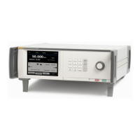
6270A
Operators Manual
30
Table 8. Rear-Panel Features (cont.)
Item Description
IEEE-488 Connector
IEEE-488.2 remote operation interface. Refer to the Remote Programmers
Manual for more information on remote operation.
RS-232 Connector
RS-232 remote operation interface. Refer to the Remote Programmers
Manual for more information on remote operation.
AC PWR INPUT
Connector
A grounded male three-prong connector that accepts the mains power cord.
Master ON/OFF Switch
Supplies and disconnects mains power to the unit. This switch must be in
the ON (I) position before the Standby button on the front panel will
function.
F1 Fuse Holder
Line power fuse. See Fuse Replacement for fuse rating information and the
fuse replacement procedure.
Chassis Ground
Pem Nut
A Pem nut that is internally grounded to the chassis. If the Product is the
location of the ground reference point in a system, this binding post can be
used for connecting other instruments to earth ground. (The chassis is
normally connected to earth ground through the three-conductor line cord
instead of through the earth ground binding post.)
Removable
Manifold/Pressure
Connection
All of the pressure connections are made on the rear panel through a
removable manifold. The manifold comes in three localized versions: NPT,
BSP, and SAE. See Rear-Panel Manifold Pressure Connections for more
information. See Specifications for pressure limitations for each port.

 Loading...