NetTool
Users Manual
3-6
Polarity information is also given. The waveform-shaped
icons used in the diagram are listed in Table 3-3.
Table 3-3. Link and Polarity Level
Indicator Definition
Normal level, normal polarity
Normal level, reverse polarity
Low level, normal polarity
Low level, reverse polarity. Link level is
displayed by the height of the waveform.
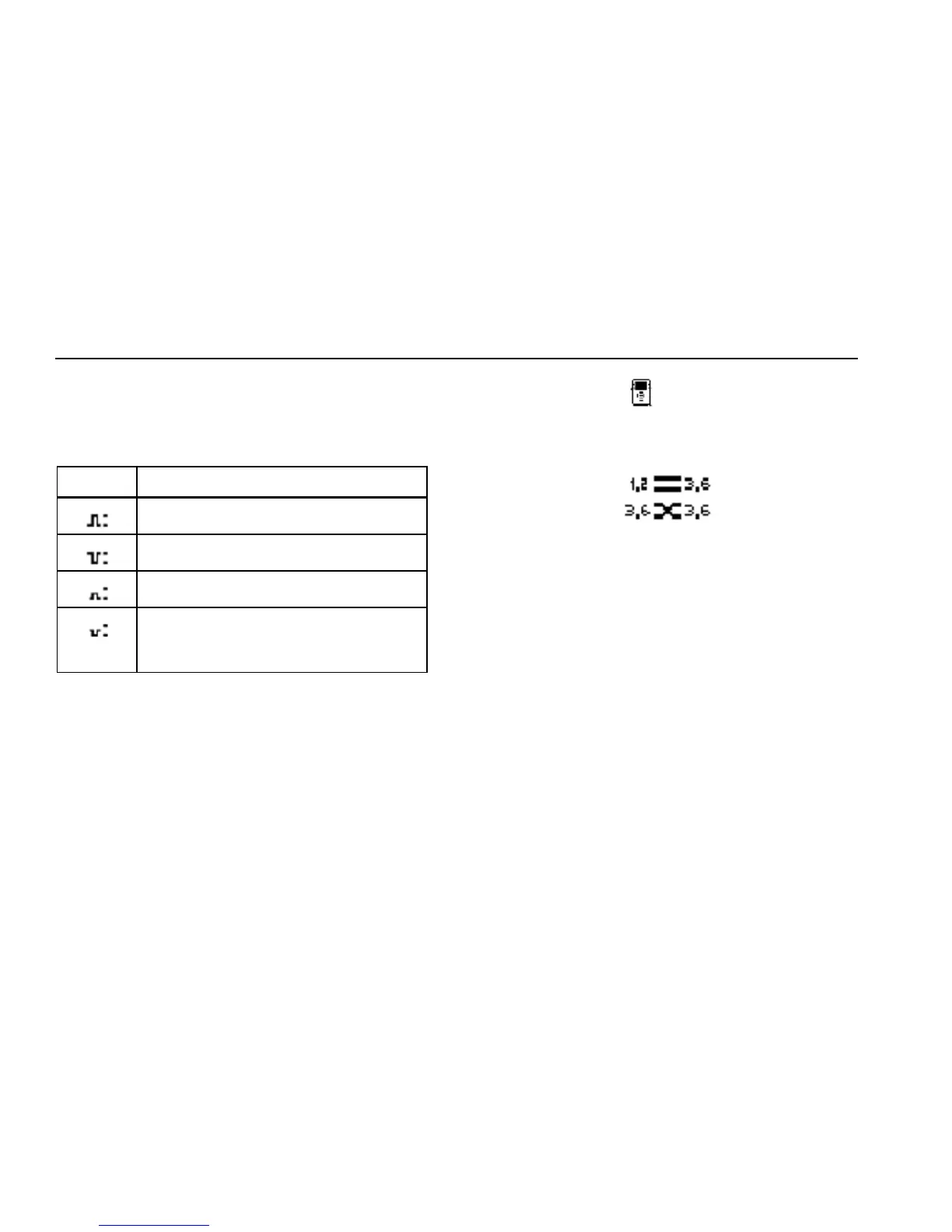
Under the NetTool icon
, you can also obtain status
information for the cables connected to NetTool. For
example:
ahn235f.eps
The tester detects whether the cables are straight or
swapped. If it sees a swap cable problem, it swaps the
cables internally, allowing you to troubleshoot past a
simple swap cable problem.
The LEDs on either side of NetTool indicate the status and
utilization of the link and whether NetTool discovers any
errors.