AutoTest
Running AutoTest
3
3-7
To get detailed results, move the cursor to one of the
following icons then press SELECT:
• PC icon : enables you to view results for the
device. Go to Chapter 4 “Troubleshooting a
Network Device” for details.
• Network icon
: enables you to view
network results. Go to Chapter 5
“Troubleshooting Networks” for details.
You can view additional results by selecting items from the
Main menu below the diagram.
Inline between a PoE Powered Device and the
Network
During AutoTest, NetTool checks for a network on one
side and an Ethernet termination on the other. If this
configuration is found, the sides are connected together
for up to 20 seconds while NetTool searches for a link
pulse. This enables an Ethernet-powered device to power
up and source link to complete the connection.
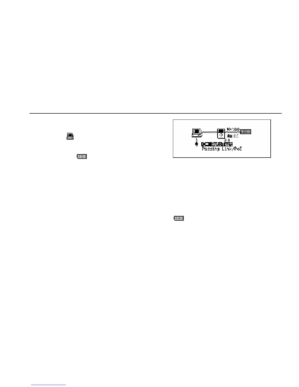
If NetTool is connected between a PoE-powered device
and the network, a diagram similar to the one shown in
Figure 3-6 is displayed.
ahn311s.bmp
Figure 3-6. Inline Connection Between a PoE-Powered
Device and the Network
The diagram in Figure 3-6 also shows the speed of the
link. Icons represent duplex settings (see Table 3-2) and
link and polarity levels (see Table 3-3). Status information
is displayed in the area below “AutoTest”.
To get detailed results on the network, select the Network
icon
.
For VoIP-specific information, see Chapter 7 “Verifying
Voice over IP Service”.