12CI400A • 12HI400A 15
How the unit works — models with lever dispensing
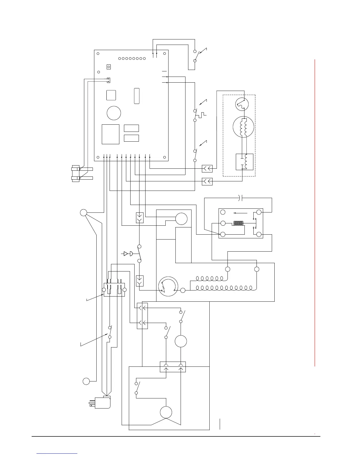
The dispense wheel motor is energized through the power, dispense and cover interlock switches. The bin signal circuit is completed through the normally
closed contacts of the bin thermostat and the bin signal switch. When ice builds up around the bin thermostat, the contacts opens, cutting the bin signal
circuit.
BLACK
#41
MOTOR
BLACK
#33
BLACK
BLACK #29
WHITE #17
COMP.
SWITCH
COMM.
WHITE
COMPRESSOR
COMP. START RELAY
MAIN FRAME
MOUNTED ON
COMPONENTS
WHITE #34
M
#42
BLACK
STA RT
RUN
ORANGE #23
COMP. START
CAPACITOR
R
S
BLACK
L
#42
S
1
UP
M
2
4
SOLENOID
ON SPLASH PANEL
COMPONENTS MOUNTED
WATER
#30
BLACK
WHITE
#32
S
BLACK #31
4
1
C
1
#28
BLACK #22
MAIN FRAME
(INTERNAL)
MOUNTED ON
COMPONENTS
OVER-LOAD
COMPRESSOR
BLACK #14
WHITE #16
FAN
STA RT
RELAY
YELLOW
BLACK
GEAR MOTOR
BLUE
BLACK #18 BLACK #19
WHITE #15
BLACK #20
VAC
LINE
RED #20
RED #20
24
VAC
GREEN #12
WHEEL
4
GREEN
BLACK #24
1
#21
RED
BLACK #25
WHITE #26
BLACK
WHITE
8
7
BLACK #13
6
5
SAFETY SWITCH
HIGH PRESSURE
RED #46
4
3
2
1
WHITE #11
BLACK #10
GREEN #27
x
SENSOR
WATER
DRIVE
FAN
L2
COMP.
L2
SOFTWARE
I.D.
L2
L2
L2
L1
L1
EARTH
I.D.
LABEL
B-E
2ND
60M
WTR
B-T
20M
C
DR
RESET
POWER
x
MAIN FRAME
GRN TO
60 HZ
POWER SWITCH
TERMINAL BLOCK
ELEC. BOX
GRN IN
WATER SENSOR
CLOSED COMP. OFF)
(OPEN COMP. ON,
COMPRESSOR SWITCH
2. HIGH PRESSURE SAFETY SWITCH:
OPEN: 425psi CLOSES: 297psi (AUTORESET)
SEE LABLE FOR PROPER ORIENTATION
1. COMPRESSOR START RELAY IS GRAVITY SENSITIVE.
NOTE
2
3
4
T.O.L.
115 VAC
BIN LEVEL
SWITCH
STA RT
RUN
801 Church Lane
Easton, PA 18040 USA
For service call:
Toll free (877) 612-5086 or
+1 (610) 252-7301
On the web: www.follettice.com
208581R04
THERMOSTAT
Wiring diagram – models with lever dispensing




 To Next Page