16 12CI400A • 12HI400A
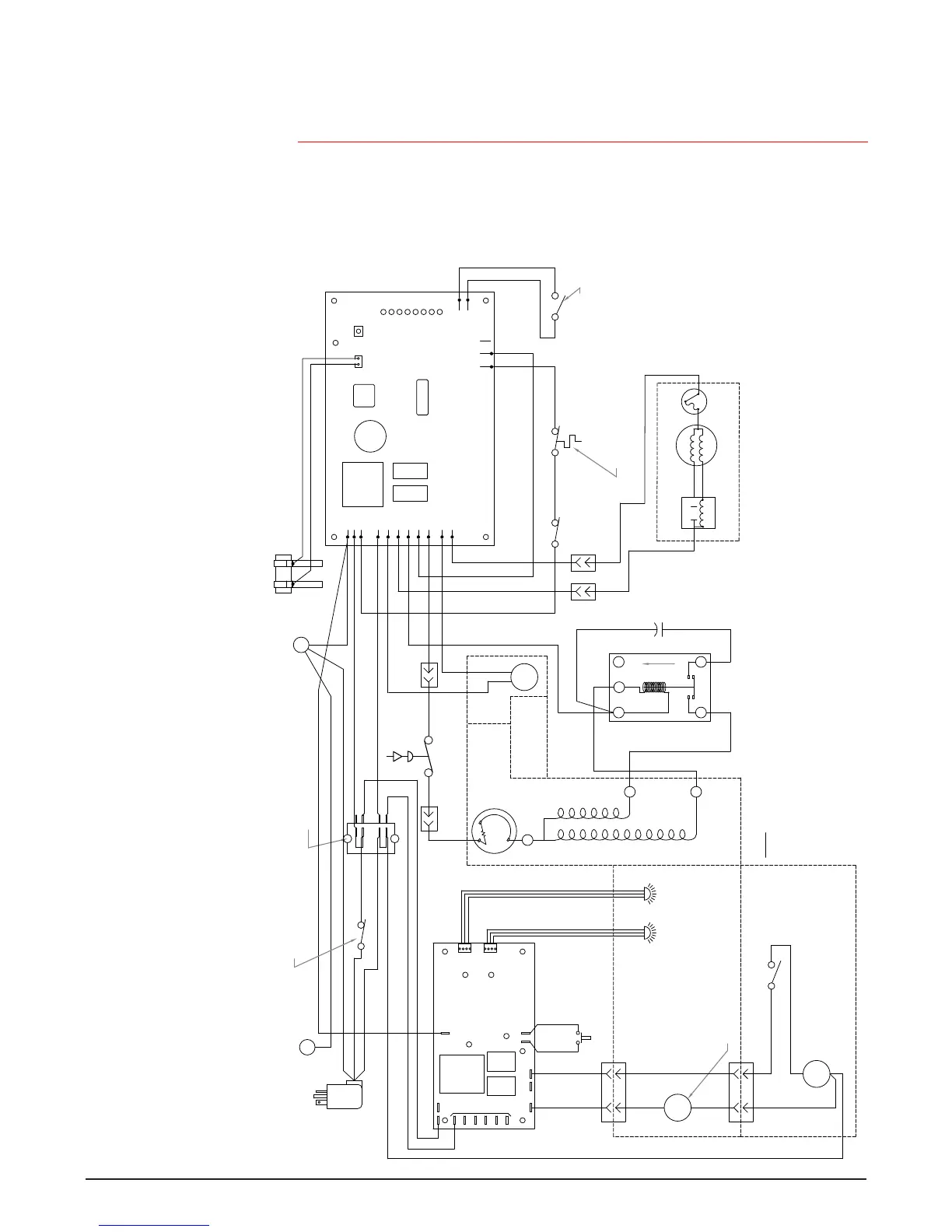
Wiring diagram – models with SensorSAFE infrared dispensing
How the unit works — models with SensorSAFE infrared dispensing
Models with SensorSAFE infrared dispensing provide “touchless” ice and water dispensing. When a container is placed within the actuation zone below the ice or water
chute, an invisible, randomly-generated infrared signal is emitted, reected off the container and detected by the sensor. The sensor then sends a signal to the control board
to activate the appropriate components to dispense ice or water. LEDs on the board indicate when the board is receiving a signal from the sensors. A safety, shut-off feature
automatically shuts off dispensing after one minute of continuous activation. Dispensing can be restarted by moving the container away and then returning it to the actuation
zone. Dispensing can be temporarily suspended by depressing and releasing the clean switch, located under the left side of the top front cover. Depressing and releasing the
button a second time will return the dispenser to normal operating state. If the clean switch is not depressed a second time, the dispenser will automatically resume normal
dispense operation (CLN LED goes out) after two minutes. An LED on the control board will light to indicate that the dispensing has been suspended by activation of the clean
switch. The bin signal circuit is completed through the normally closed contacts of the bin thermostat and the bin signal switch. When ice builds up around the bin thermostat,
the contacts open, cutting the bin signal.
801 Church Lane
Easton, PA 18040 USA
For service call:
Toll free (877) 612-5086 or
+1 (610) 252-7301
On the web: www.follettice.com
208580R05
12 Series with SensorSAFE
SOL
WTR
NEUTRAL
CLN
WM
PWR
WTR
L1
GND
ICE
COMM.
SWITCH
COMP.
MOUNTED ON
WATER
COMPRESSOR
WHITE #34
BLACK #41
WHEELMOTOR
M
COMPONENTS
MOUNTED ON
MAIN FRAME
BLACK #33
1
SOLENOID
4
SPLASH PANEL
COMP. START RELAY
#37
WHITE
S
#36
BLACK
BLACK #25
STA R T
BLACK
BLACK #35
COMPONENTS
SENSOR
WATER
SENSOR
ICE
CLEAN SWITCH
ORANGE #23
R
RUN
BLACK
S L
S
UP
M
1 2
#40
#40
YELLOW
YELLOW
BLACK #24
41
MAIN FRAME
BLACK #22
COMPRESSOR
OVER-LOAD
COMPONENTS
MOUNTED ON
(INTERNAL)
C
WHITE #16
FAN
#42
STA RT
START
RELAY
COMP. START
CAPACITOR
BLACK
YELLOW
MOUNTED ON MAIN FRAME
#42
3
4
2
RUN
WHITE
BLUE
GEAR MOTOR
BLACK #19BLACK #18
BLACK #20
WHITE #15
WHITE #17
BLACK #14
RED #20
24
LINE
VAC
VAC
RED #20
GREEN #12
RED #46
115 VAC
GREEN
WHITE #44
BLACK #43
WHITE #26
WHITE
BLACK
BLACK #13
HIGH PRESSURE
SAFETY SWITCH
RED
#21
8
4
7
3
6 2
5
1
WHITE #11
BLACK #10
GREEN #45
GREEN #27
TERMINAL BLOCK
x
LABEL
I.D.
I.D.
SOFTWARE
COMP.
FAN
DRIVE
L2
L2
EARTH
L2
L2
L2
L1
L1
B-E
B-T
WTR
60M
2ND
SENSOR
C
20M
DR
WATER
RESET
POWER
GRN TO
MAIN FRAME
x
GRN IN
ELEC. BOX
WATER SENSOR
POWER SWITCH
1. COMPRESSOR START RELAY IS GRAVITY SENSITIVE.
SEE LABEL FOR PROPER ORIENTATION
NOTE
CLOSED COMP. OFF)
(OPEN COMP. ON,
COMPRESSOR SWITCH
BIN LEVEL THERMOSTAT
BIN SIGNAL SWITCH
OPEN: 425psi CLOSES: 297psi (AUTORESET)
2. HIGH PRESSURE SAFETY SWITCH:
T.O.L.
60 HZ