18 12CI400A • 12HI400A
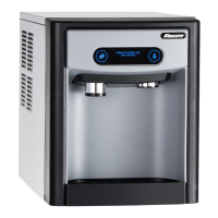
Normal operation – Stage 2
The water sensor veries water in the oat reservoir. The water OK LED (WTR) comes on. At the same time,
the gearmotor, compressor and condenser fan motor come on, lighting the drive LED (DR) and compressor
LED (C). The high initial current draw of the compressor run winding closes the contacts of the current relay
energizing the start winding through the run capacitor. The gearmotor is also started through a current style
relay (or start capacitor) that is pulled in by the initial high current draw of the run winding. The PWR, B-E and
WTR LED remain on.
GRD
L1
L1
L2
L2
L2
L2
L2
COMPRESSOR
FAN
DRIVE
DR
C
20M
60M
2ND
WTR
B-T
B-E
RESET
GRD
G
B
W
FAN
BLACK
WHITE
BLACK
BLACK
R
ORANGE
S
S
L
COMPRESSOR
C
RED
BLACK
BLACK
INPUT
POWER
WATER
SENSOR
CONTROL
BOARD
BLACK
24V
COMMON
LINE VAC
RED
RED
WHITE
BLACK
BIN T-STAT
BIN SIGNAL
FROM DISPENSER
JUNCTION BOX
(MCD400A/WVS series –
blk wire is on 24V)
WHITE
RED
WHITE
M
1
COMPRESSOR
SWITCH
PWR
BLACK
T.O.L.
BLACK
RED
HIGH PRESSURE
SAFETY SWITCH
M
WHITE
WHITE
BLUE
RELAY
START
T.O.L.
BLACK
4
2
3
YELLOW
GEAR MOTOR
STA RT
RUN
GRD
L1
L1
L2
L2
L2
L2
L2
COMPRESSOR
FAN
DRIVE
DR
C
20M
60M
2ND
WTR
B-T
B-E
RESET
GRD
G
B
W
FAN
BLACK
WHITE
BLACK
BLACK
R
ORANGE
S
S
L
COMPRESSOR
C
RED
BLACK
BLACK
WHITE
INPUT
POWER
WATER
SENSOR
CONTROL
BOARD
BLACK
24V
COMMON
LINE VAC
RED
RED
WHITE
BLACK
BIN T-STAT
BIN SIGNAL
FROM DISPENSER
JUNCTION BOX
(MCD400A/WVS series –
blk wire is on 24V)
WHITE
RED
WHITE
M
1
COMPRESSOR
SWITCH
PWR
BLACK
T.O.L.
BLACK
RED
HIGH PRESSURE
SAFETY SWITCH
M
WHITE
BLUE
RELAY
START
T.O.L.
BLACK
4
2
3
YELLOW
GEAR MOTOR
STA RT
RUN
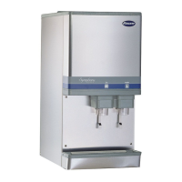
Normal operation – Stage 3
After the initial high current draw drops off, the gearmotor start relay contacts open, dropping out the start
winding (or start capacitor). As the compressor comes up to normal running speed, the compressor start relay
contacts also open, dropping out the start winding of the compressor. The ice machine is now in a normal
icemaking mode. The ice machine will begin to produce ice and continue to produce ice until the bin level
control in the ice dispenser is satised. The PWR, B-E, DR, C and WTR LEDs are all on.