46
CHECK AND SETTING OF THE ANGLES
The different positions for angle cutting have been set at the origin by the factory
Nevertheless, in order to grant a precise work, verify that all angles are correct before cutting
SETTING THE CUT-END GUIDE FOR 90° CUT
Make sure that the disk is perpendicular to the guide.
1. Block the mitre saw’s head in the low position, close the lock-knob in the transport position
(see Fig.1).
2. Loosen the base rotation knob and position it at 0°. Re-tighten the base rotation knob
3. Loosen the head bevel knob located on the back of the machine and set the position the
head at 0°. Tighten again the head bevel knob.
4. Position one of the sides of a square (not delivered) against the cut-end guide and the
other side against the disk of the mitre saw. Make sure that the square is correctly
positioned along the disk, but not touching the teethes. When the square is correctly
positioned, its two sides must show a continuous contact with the disk and the cut-end
guide
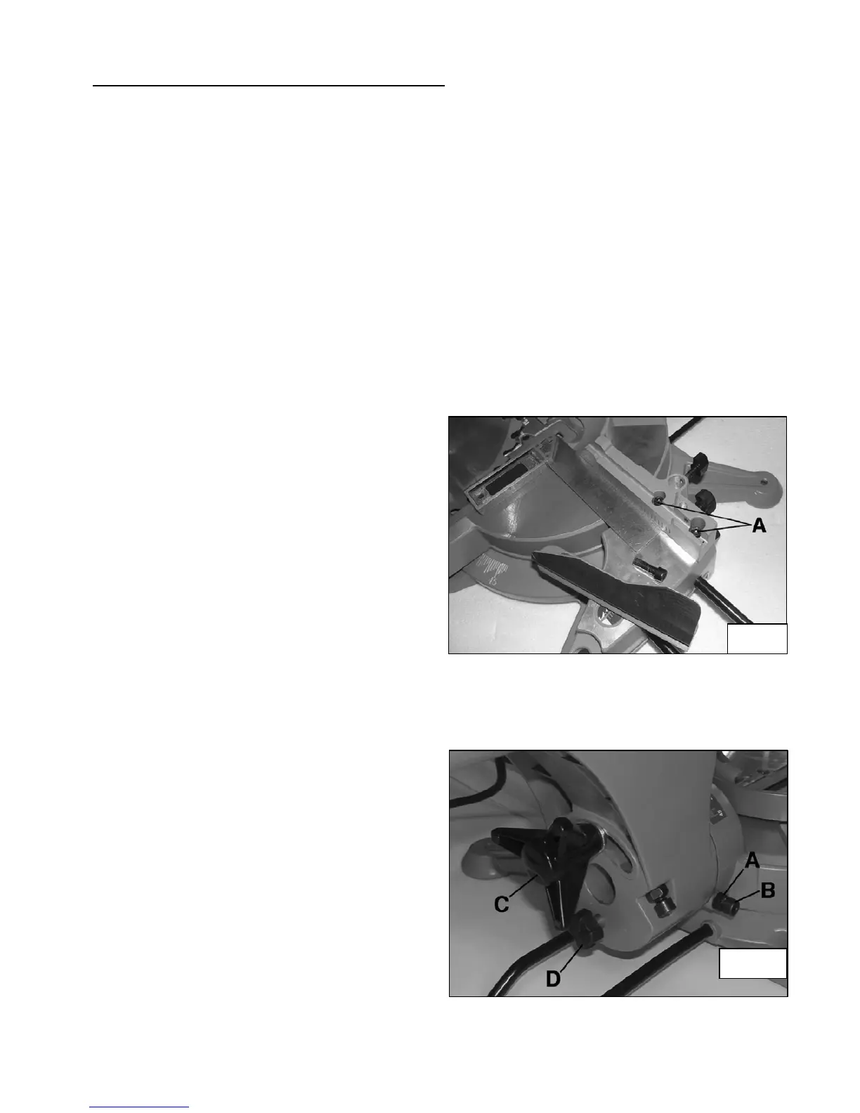
5. If this is not the case you can set the cut-end guide as follows:
Loosen the hexagonal screws and the
two knobs fixing the guide extensions.
Slide out the two extensions and pull
them off.
Loosen the 4 hexagonal screws (A)
Fig.9 of the two sides of the cut-end
guide.
Position the square against the disk
and move the cut-end guide until it
shows a continuous contact with the
other side of the square.
Tighten the 4 hexagonal screws (A)
and reassemble the cut-end guide
extensions.
SETTING THE UPPER TABLE
Make sure that the disk of the mitre saw is perpendicular with the base of the machine.
Block the mitre saw’s head in the low position,
close the lock-knob in the transport position (see
Fig.1).
1. Loosen the rotating base knob and position
the base at 0°. Tighten the knob.
2. Loosen the head bevel knob located on the
back of the machine and set the position
the head at 0°. Tighten again the head
bevel knob.
3. Position one of the sides of a square (not
delivered) on the table and the other side
against the disk of the mitre saw. Make
sure that the square is correctly positioned
along the disk, but not touching the
teethes. When the square is correctly positioned, its two sides must show a continuous
contact with the disk and the table.
Fig.9
Fig.10