INSTALLATION AND SETUP
Electrical Installation
23
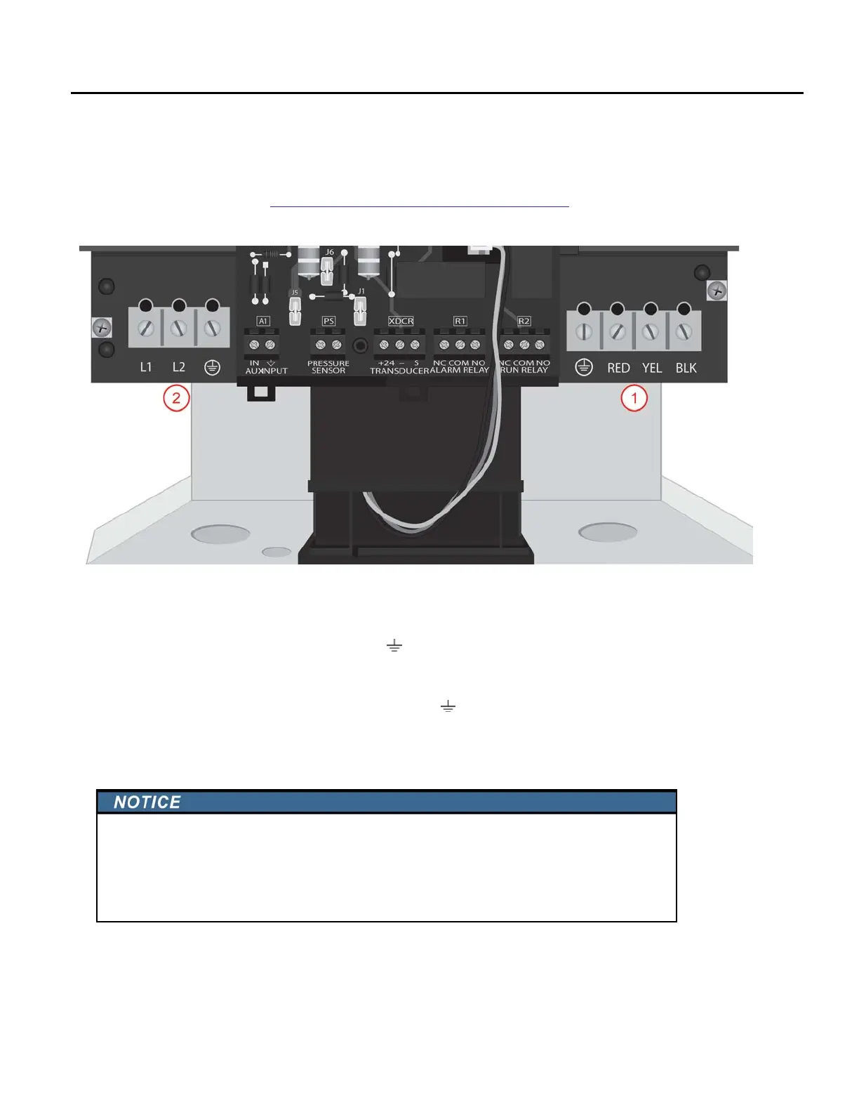
Power Circuit and Motor Connections
Drive is suitable for use on a circuit capable of delivering not more than 5000 RMS symmetrical
amperes, 250 volts maximum.
Verify that the dedicated branch circuit for the SubDrive/MonoDrive is equipped with a properly-
siz
ed circuit breaker. Refer to
“Fuse/Circuit Breaker and Wire Sizing” on page 20 for minimum
breaker size.)
Verify that the power has been shut off at the main breaker.
1. Feed the motor leads through the opening on the bottom right side of the drive and connect
them t
o the terminal block positions marked
(Green Ground Wire), Red, Yellow
and Black. Tighten terminals to 15 in-lbs (1.7 Nm).
2. Feed the 230 VAC power leads through the larger opening on the bottom left side of the drive
and c
onnect them to the terminals marked L1, L2, and
. Tighten terminals to 15 in-lbs (1.7
Nm).
NOTE: These t
erminals accept wire sizes from 6 to 20 AWG.
Risk of damage to Drive, or malfunction can occur.
• For retrofit application (i.e. MonoDrive), make sure to check the integrity of power and
motor leads. This requires measuring the insulation resistance with a suitable megohm-
meter.
• Refer to AIM Manual for specifications.
 Loading...