Cab Load Disconnect Switch
WARNING
Turning the cab load disconnect switch (CLDS) to
the off position does not disconnect the connec-
tion between the battery and the starter. To work
on the vehicle safely, the negative leads must be
disconnected from the battery.
IMPORTANT: The ignition should be turned off
before turning the CLDS to on or off.
The CLDS is used to avoid excessive draw on the
battery when the vehicle is parked for an extended
period of time by disconnecting (or opening) the con-
nection between the battery and the most of the ve-
hicle electrical system.
The CLDS may be mounted:
•
inside the cab on the outboard side of the
driver’s seat;
•
at the battery box;
•
outboard on the left frame rail.
See
Fig. 3.6 for an EPA07 CLDS; see Fig. 3.7 for an
EPA10 and newer switch.
If the CLDS is turned to the off position while the ve-
hicle is running, the emergency power system will
activate. The powertrain PDM will receive power from
the emergency power feed, but the batteries will not
be charging. See the Emergency Power Supply
heading below for details.
Emergency Power Supply
The Cascadia electrical system has an emergency
power circuit that supplies battery power for exterior
lighting. This assists vehicle visibility in the event a
MEGA fuse is open circuit. The emergency power
circuit is live even when the CLDS is turned off.
The emergency power supply feature allows for the
vehicle to be driven off the highway and for the exte-
rior lighting to remain on in the event of a SAM Cab
or SAM Chassis failure. The emergency power sup-
ply will cause certain exterior lamps to flash (depend-
ing on if it is the SAM Cab or SAM Chassis that
failed), indicating that the vehicle is disabled.
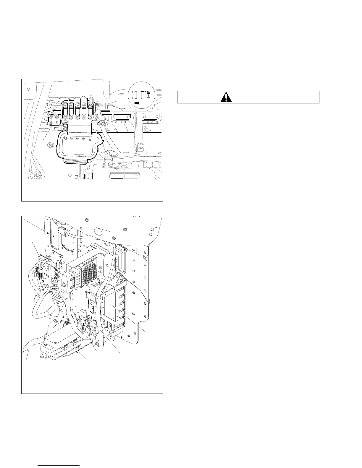
06/15/2007 f545073
1
2
1. MEGA Fuse Junction Block
2. Main Ground Junction Block
Fig. 3.2, EPA07 MEGA Fuse Junction Block
02/27/2012 f545682a
1
3
2
4
1. Powertrain PDM (PT-PDM)
2. Inline Fuse, Auxiliary PDM
3. SAM Chassis
4. Powernet Distribution Box (PNDB)
Fig. 3.3, Engine Compartment Power Distribution
Components
Electrical System
3.3