Instrumentation Control Units
The instrumentation control unit (ICU) provides the
driver with engine and vehicle information. It is com-
prised of standard and optional gauges, an audible
warning, a driver message center, and a lightbar con-
taining warning and indicator lamps (also known as
telltales). Warning and indicator lamps illuminate in
red (danger), amber (caution), green (status advi-
sory), or blue (high-beam headlights active).
Cascadia vehicles are equipped with an ICU3, ICU4,
ICU4M, or ICU4Me. See
Fig. 4.1, Fig. 4.2, and
Fig. 4.3 for typical ICU layouts.
The following headings in this chapter provide addi-
tional information and operating instructions for ICU
components:
•
"Warning and Indicator Lights"
•
"Instruments"
•
"Driver Message Center"
Ignition Sequence
When the ignition is turned on, the ICU runs a self-
check. See Fig. 4.4. Observing the ignition sequence
is a good way to ensure the ICU is functioning prop-
erly.
IMPORTANT: Do not crank the engine until the
ICU self-check is complete.
NOTE: Air gauges do not complete a sweep of
their dials during the ignition sequence.
When the ignition is turned on, the following actions
should occur:
•
electronic gauges complete a full sweep of
their dials
09/10/2009 f610864a
1
2
3
4
5
6
7
8
9
13
10
11
12
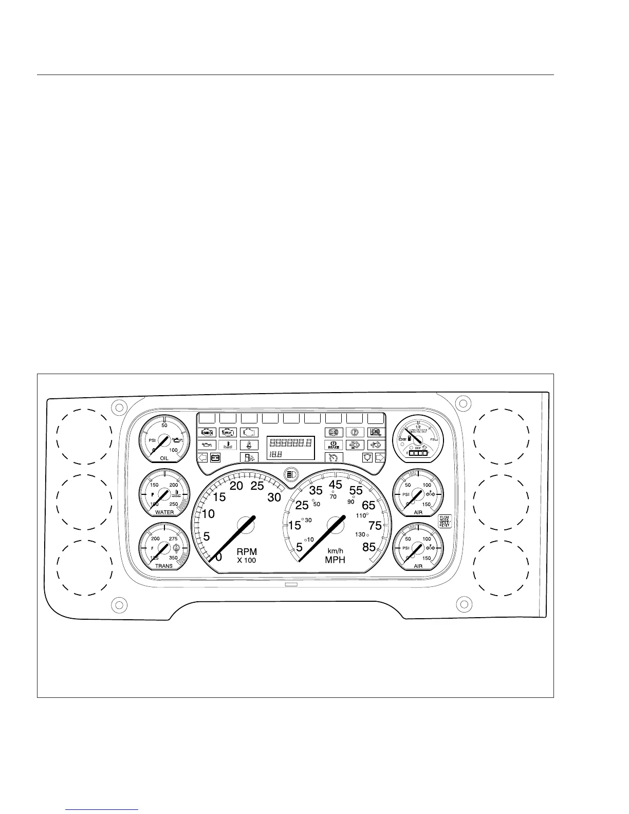
1. Transmission Temperature Gauge
2. Coolant Temperature Gauge
3. Engine Oil Pressure Gauge
4. Driver Message Center
5. Fuel/DEF Level Gauge
6. Primary Air Pressure Gauge
7. Secondary Air Pressure Gauge
8. Speedometer
9. Tachometer
10. High Beam Indicator
11. Driver Display Screen
12. Mode/Reset Switch
13. Satellite Gauges
Fig. 4.1, ICU3 Instrument Cluster (EPA10 shown)
Instruments
4.1