S90-010 M FRICK
QUANTUM™ COMPRESSOR CONTROL PANEL
Page 18 MAINTENANCE
DIGITAL BOARD SETTINGS
COMMUNICATIONS SETTINGS
J5
in
out*
120 ohm long communications line
termination.
No termination.
J7
in
out*
RS-422/485 transmit pull-up for long
communications lines.
No pull-up.
J8
in
out*
RS-422 transmit pull-up for long
communications lines.
No pull-up.
J9
in
out*
RS-422/485 receive pull-down for long
communications lines.
No pull-down.
J10
in
out*
RS-422 receive pull-down for long
communications lines.
No pull-down.
* = standard setting
DIPSWITCH SETTINGS
SW1 SW2 SW3 SW4 SW5 SW6
Board #1 on on on on off on
Board #2 off on on on off on
Board #3 on off on on off on
Board #4 off off on on off on
Board #5 on on off on off on
Board #6 off on off on off on
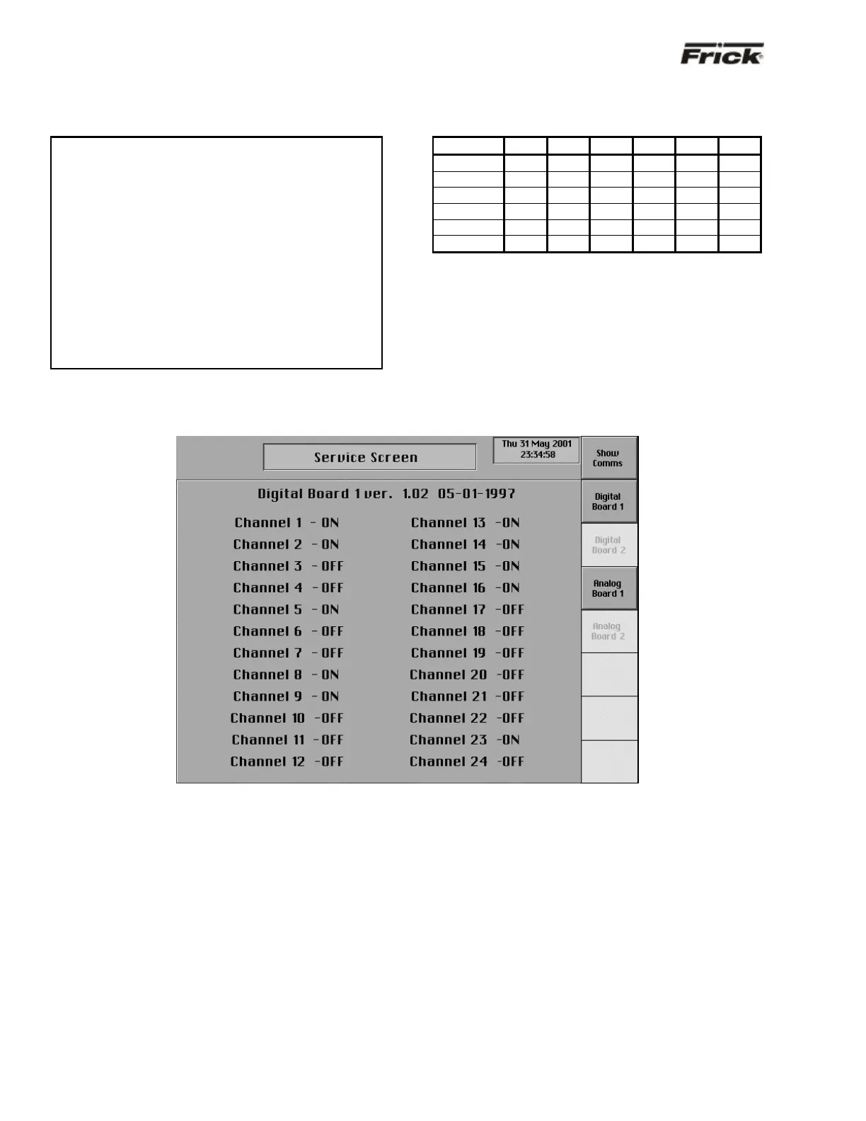
“Service Screen” - Digital Board Inputs and Outputs
The “Service Screen” has been provided to view the raw
data from a Digital Board. There is a separate screen for
each of the Digital Boards that are present. Digital values
are shown as ON or OFF.
To access the “Service Screens” from the “Operating
Status” screen, press the [MENU] key, then the [MORE…]
key, and finally the [SERVICE SCREEN] key.