FRICK
QUANTUM™ COMPRESSOR CONTROL PANEL S90-010 M
MAINTENANCE Page 5
QUANTUM™ CONTROLLER BOARD IDENTIFICATION
INTRODUCTION
Frick
Controls has over the years, strived to remain on
the cutting edge of microprocessor technology and
development. In addition, because of the ever-increasing
speed, memory, features, and power of microprocessors,
Frick
Controls will continue to introduce the latest
advancement in microprocessor control technology.
Our microprocessor family has shared the name
Quantum™, over the past six years. There are currently
four controllers within this family. The first two of these
controllers (known as Quantum™ 1 and Quantum™ 2) are
no longer in production, and as such, will not be further
mentioned in this manual. The two current members in
production of the Quantum™ family are the Quantum™ 3,
and the Quantum™ 4. It is critical to the end user to be
able to identify the differences between these controllers.
Refer to the section in this manual entitled “Quantum™ 3
Main Board History and Identification” and “Quantum™ 4
Main Board History and Identification” for additional
information as to how to identify the particular Quantum™
controller that you have.
Throughout this manual, the two different controllers will
be talked about for the most part as one (as they do
function the same). Please note however that there is a
separate section for both the Quantum™ 3 and for the
Quantum™ 4, where all of the individual specifics are
identified and explained. This is why it is important for you
to be aware of which version of Quantum™ board you
have.
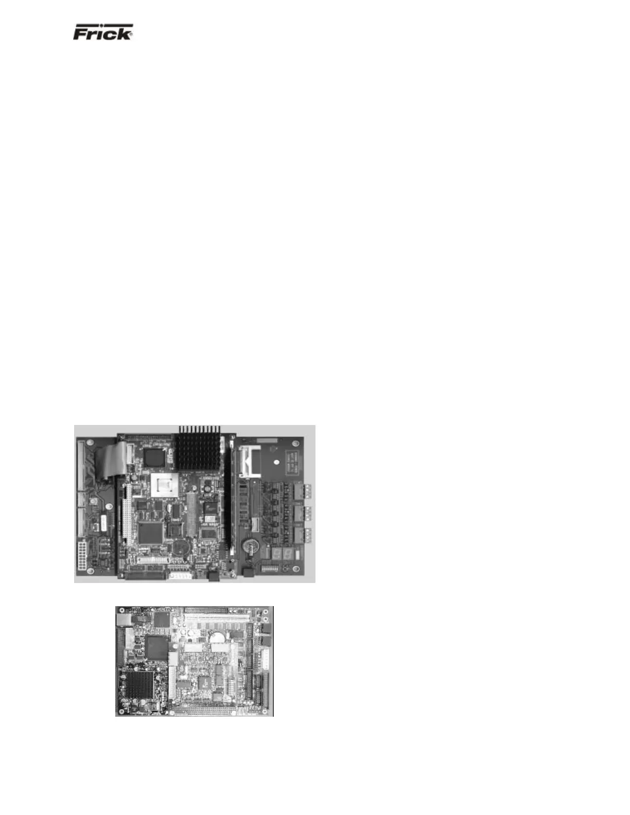
Quantum™ 3
Quantum™ 4
TROUBLESHOOTING
THE QUANTUM™ CONTROL PANEL
This section contains information on troubleshooting and
making corrections to the boards and control circuits of the
Quantum™. Reference the drawings at the end of this
manual.
GENERAL INFORMATION:
The components within the control panel can be
inadvertently damaged by static electricity or
mishandling. Only qualified technicians should
directly handle these components.
1. DO NOT attempt to make corrections to the
power supply without shutting off the power to the
control panel. Accidental shorts can irreparably
damage the processor boards or the display
screen.
2. DO NOT HANDLE the panel boards when their
cables are disconnected without first attaching a
properly grounded wrist ground strap to prevent
static electrical discharge from your body.
Most problems encountered with the microprocessor and
control circuits will be the result of a wiring fault, a blown
fuse, faulty I/O module or failure of a peripheral control
such as a solenoid coil or a pressure transducer. Faults in
the computer, while possible, are unlikely. If a fault
develops in the computer, the probability is that all
functions will cease and the display screen will go blank.
The control system of the compressor consists of an AC
(high voltage) side, which can be either 120 volts, or 230
volts, and a DC (low voltage) side. The AC side actuates
solenoids, relays, alarms, and other electromechanical
functions. The DC side operates the computer and it's
various sensors.
When working within the panel, the AC high voltage
side, which can be either nominal 120 VAC or nominal
230 VAC, CAN CAUSE INJURY OR DEATH.
To troubleshoot the low-voltage side of the control circuits,
it is necessary to have the following tools:
1. Accurate digital multimeter (capable of reading to
the hundreds of a volt)
2. Small wire stripper
3. Small screwdriver (with insulated shaft)
4. Small snip nose pliers
5. Wrist Grounding strap
2
6. Static free grounded work surface
Note: Proper panel voltage refers to the AC (high volt-
age) that has been supplied to the panel, which could
be either nominal 120 VAC or nominal 230 VAC
(Reference the Control Panel Power Specifications).
Some problems that are encountered involve
troubleshooting the panels digital inputs and outputs. The
Digital I/O (Input/Output) boards have six Digital I/O (DIO)
board connectors labeled P1 through P6. The input and
output modules are wired into a DIO connector plug.
Position 3 provides power and position 4 is a neutral on
the DIO connectors.