S90-010 M FRICK
QUANTUM™ COMPRESSOR CONTROL PANEL
Page 26 MAINTENANCE
ANALOG BOARD #2 OUTPUT JUMPERS
Output Channel #1 – PID / Programmable
J26 1-2
2-3
0-20 mA Output
4-20 mA Output
J39 1-2
2-3
4-20 mA Output
0-20 mA Output
IC’s install U15 & U7 Connect to P10 terms 1 & 2
Output Channel #2 - PID / Programmable
J25 1-2
2-3
0-20 mA Output
4-20 mA Output
J40 1-2
2-3
4-20 mA Output
0-20 mA Output
IC’s Install U15 & U6 Connect to P10 terms 3 & 4
Output Channel #3 – Variable Speed Motor Drive
J24 1-2
2-3*
0-20 mA Output
4-20 mA Output
J41 1-2*
2-3
4-20 mA output
0-20 mA output
IC’s install U15 & U5 Connect to P10 terminals 5 & 6
Output Channel #4 - Condenser**
J23 1-2
2-3*
0-20 mA Output
4-20 mA Output
J42 1-2*
2-3
4-20 mA Output
0-20 mA Output
IC’s Install U15 & U4 Connect to P10 terminals 7 & 8
* = Standard Setting
** = If applicable
Note: IC’s must also be installed in order to enable the
analog output options. U15 along with at least one IC
(U4, U5, U6, or U7) installed will enable the channel.
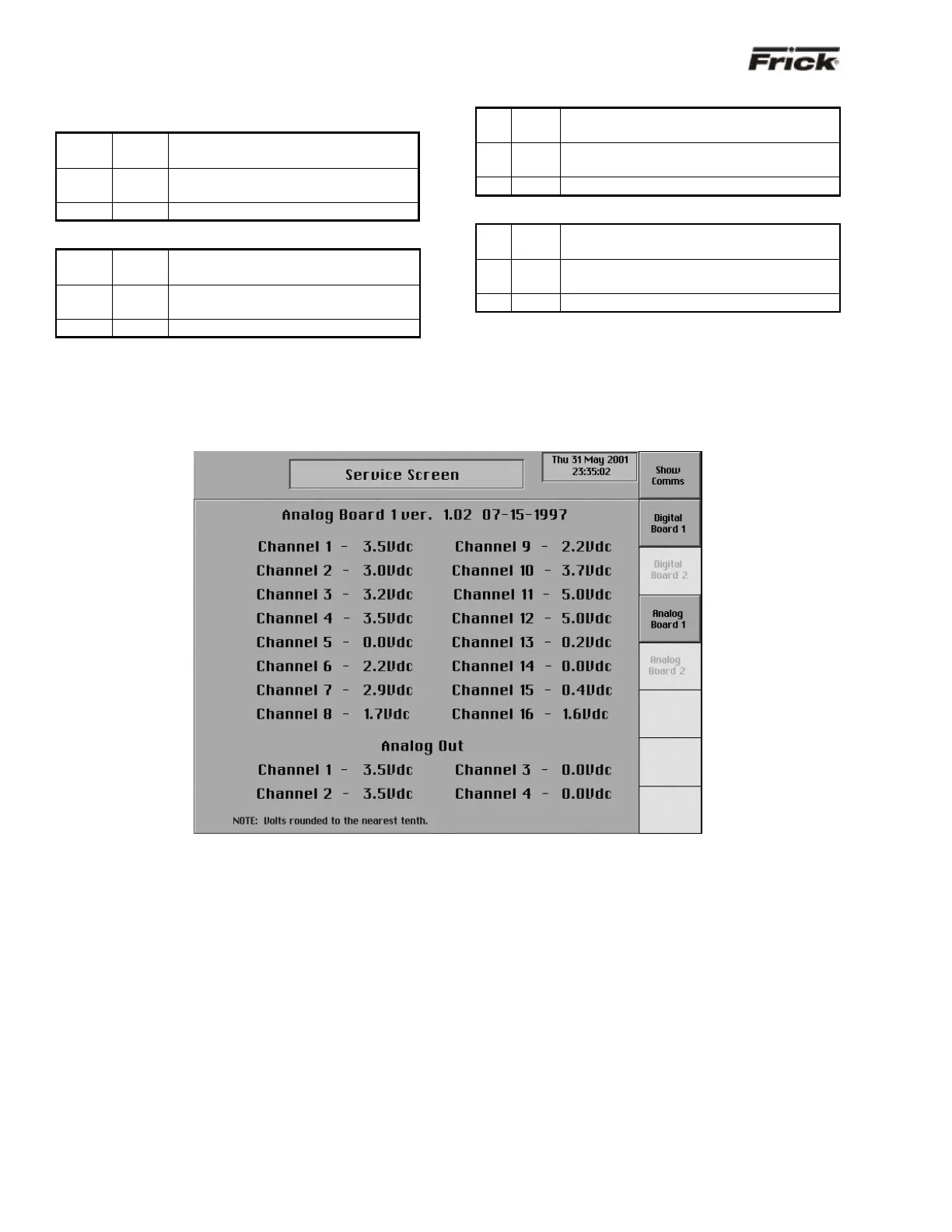
“Service Screen” - Analog Board Inputs and Outputs
The “Service Screen” has been provided to view the raw
data from an Analog Board. There is a separate screen for
each of the Analog Boards that are present. Analog values
are converted from binary to show volts. The error factor is
± .05 volts.
To access the “Service Screens” from the “Operating
Status” screen, press the [MENU] key, then the [MORE…]
key, and finally the [SERVICE SCREEN] key.