S90-010 M FRICK
QUANTUM™ COMPRESSOR CONTROL PANEL
Page 40 MAINTENANCE
SYMPTOM PROBABLE CAUSES and CORRECTIONS
CONTROL PANEL DOES NOT
RESPOND TO REMOTE CONTROL
SIGNALS
Digital I/O Board 2, Inputs 3 through 5 can be used to operate the compressor
from a remote location. NOTE: Check the Operating display to verify that
the compressor and the Slide Valve are in REMOTE.
If the Input 3 (MOD 3) does not turn on, check if the LED (D3) is lit when it
should be. If it isn’t, check the fuse (F3) and if the fuse is OK, check the input
module (MOD 3).
If the Input 4 (MOD 4) does not turn on, check if the LED (D4) is lit when it
should be. If it isn’t, check the fuse (F4) and if the fuse is OK, check the input
module (MOD 4).
If the Input 5 (MOD 5) does not turn on, check if the LED (D5) is lit when it
should be. If it isn’t, check the fuse (F5) and if the fuse is OK, check the input
module (MOD 5).
MOTOR LOAD CONTROL(FORCED
UNLOAD) OCCURS AT HIGH MOTOR
AMPS
The current transformer is used to convert the AC motor amps to a DC voltage
signal for the microprocessor. If the %FLA reading from the Operating display
is incorrect, contact the Frick
Service Department.
MOTOR LOAD CONTROL(FORCED
UNLOAD) OCCURS AT LOW MOTOR
AMPS
The current transformer is used to convert the AC motor amps to a DC voltage
signal for the microprocessor. If the %FLA reading from the Operating display
is incorrect, contact the Frick
Service Department.
PRESSURES ON THE OPERATING
SCREEN DO NOT APPEAR CORRECT
TEST 1 - Shut down the compressor and allow pressures to equalize.
Discharge pressure and oil pressure should have the same reading.
TEST 2 - If either oil pressure or discharge pressure read different pressures,
one or both transducers are at fault. Valve off the suction transducer from the
unit and open the vent valve on transducer manifold to atmosphere. If the
suction transducer reads atmospheric pressure, then the transducer in Test 1,
which agrees with the suction transducer, is correct. The transducer which
disagrees is defective.
NOTE: Reference the Pressure Transducer Conversion Data Chart.
COMPRESSOR WITH SLIDE VALVE
DOES NOT AUTOMATICALLY LOAD OR
UNLOAD*
Verify that the Slide Valve Mode [AUTO] key has been pressed and AUTO
appears under Slide Valve Mode on the “Operating Status” screen.
If the problem persists, see the Troubleshooting section SLIDE VALVE DOES
NOT LOAD and/or UNLOAD.
COMPRESSOR THAT STEPS ON
CAPACITY DOES NOT
AUTOMATICALLY LOAD OR UNLOAD*
Verify that the Capacity Mode [AUTO] key has been pressed and AUTO
appears under Capacity Mode on the “Operating Status” screen.
If the problem persists, see the Troubleshooting section COMPRESSOR
DOES NOT LOAD and/or UNLOAD.
* If applicable
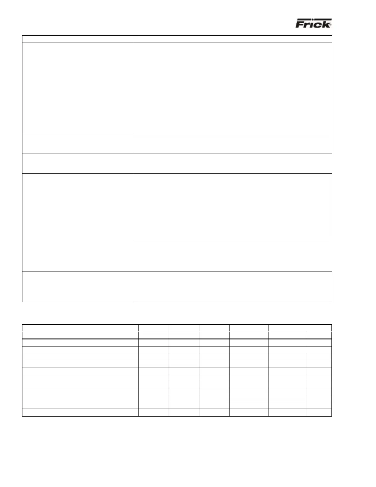
COMPRESSOR MODEL DIFFERENCES
FRICK
RWB, SC RXB* RXF RDB 3-Step RDB 4-Step
GRAM GSV, YLC GST* GSB 3-Step
Other
Slide Valve Reading
0-100% 0-100% 0-100% N/A N/A 0-100%
Slide Valve Setpoints
Yes Yes Yes N/A N/A Yes
Slide Valve Calibration
Yes Yes Yes N/A N/A Yes
Capacity Reading
N/A N/A N/A 50,75,100 25,50,75,100 N/A
Slide Stop Reading
2.2-5.0 2.2,3.5,5.0 2.2,3.5,5.0 N/A N/A N/A
Slide Stop Calibration
N/A N/A N/A N/A N/A N/A
DX Circuit Option
Yes Yes Yes N/A N/A Yes
Hot Gas Bypass/SV Setpoints Option
Yes Yes Yes N/A N/A Yes
Remote Slide Valve Position Option
Yes Yes Yes N/A N/A Yes
Sequence by Comp. Sequencing
Yes Yes Yes N/A N/A Yes
Forced unload Inhibit load delay setpoint
N/A N/A N/A Yes Yes N/A
* Or other variable VI
N/A = Not Applicable