EasyManua.ls Logo

Frick QUANTUM 4 - Adjusting

Frick QUANTUM 4
118 pages
Print Icon
To Next Page IconTo Next Page
To Previous Page IconTo Previous Page
Loading...
FRICK
QUANTUM™ COMPRESSOR CONTROL PANEL S90-010 M
MAINTENANCE Page 31
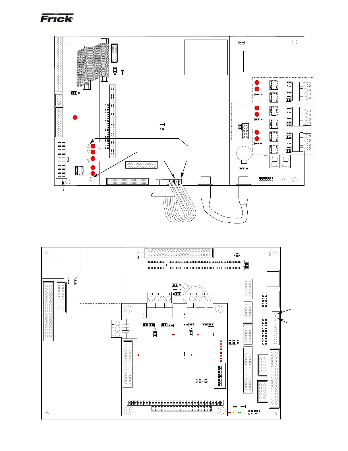
Quantum™ 3 +5 DC Voltage Measurement Location
Quantum™ 4 +5 DC Voltage Measurement Location
KB
TP3
+5
TP4
+12
TP5
-12
RX4
TX4
TP6
GND
LK11
B
A
LK10
B
A
LK7
LK8
LK24
B
A
HEAT SINK
COM2
RS232
LK19
FLASH
MEMORY
SOCKET
SW
BAT1
SW2
ON
1
2
3
4
5
6
7
8
LK20
B
A
P7
P7
TP1
GND
1
2
3
4
RS-
422
RS-
485
LK12
LK11
LK13
LK14
LK15
TX3
RX3
LK18
B
A
B
A
1
2
3
4
RS-
422
RS-
485
LK6
LK8
LK9
LK10
LK7
TX2
RX2
LK17
LK1
LK2
LK3
LK4
LK5
1
2
3
4
RS-
422
RS-
485
LK16
B
A
TX1
RX1
LK25
-12V
+5V
+12
+5 VDC
(Red lead)
Common
(Black lead)
Although power enters the board
on this connector, this is not the
recommended location for
measurement/adjustment.
Check voltages on the bottom and
top board as shown. The reading on
the top board should be between
+5.04 and +5.08 VDC, and should not
be lower than 0.10 VDC lower than
the reading on the bottom board.
Check voltages on the bottom and
top board as shown. The reading on
the top board should be between
+5.04 and +5.08 VDC, and should not
be lower than 0.10 VDC lower than
the reading on the bottom board.
PL13
LK9
LK8
LK10
PL16
PL8
PWR
SUSP
FLASH
LK11
LK12
PL24
PL3
PL
LK1
PL7
PL9
LK2
PL17
PL12
PL19
PL18
PL14
PL10
PL6
PL2
PL4
PL1
Flash Card
Socket
(Located
under
board)
PL3
PL5
PL11
LK3
A
B
LK4
PL15
TB1
TB2
LK2
COM-2
TB3
RS-232
3
2
1
LK6
B
A
LK5
LK7
COM-2
COM-1
1
2
3
4
1
2
3
4
LK8
LK7
LK10
LK9
D3
LK16
A
B
A
B
PL2
3
4
5
6
7
0
1
2
D8
D10
D11
D12
PORT 80H
D4
D5
D7
D13
SW1
ON
1
2
3
4
5
6
7
8
D6
D2
LK11
B
A
LK1
LK4
LK3
LK6
LK5
D1
D8
LK17
RS-422
RS-485
RS-422
RS-485
PL1
+5 VDC
(Red Lead)
Common
(Black Lead)
A voltage
regulator to
the flash port
allows the
Quantum™ 4
5 VDC to be
set to +5.15
VDC as
measured
here.

Table of Contents

Other manuals for Frick QUANTUM 4

Related product manuals