36
Connecting the inverter to the public grid (AC)
Monitoring the
grid
IMPORTANT! To provide the best possible grid monitoring, the resistance in the leads to
the mains connections should be as low as possible.
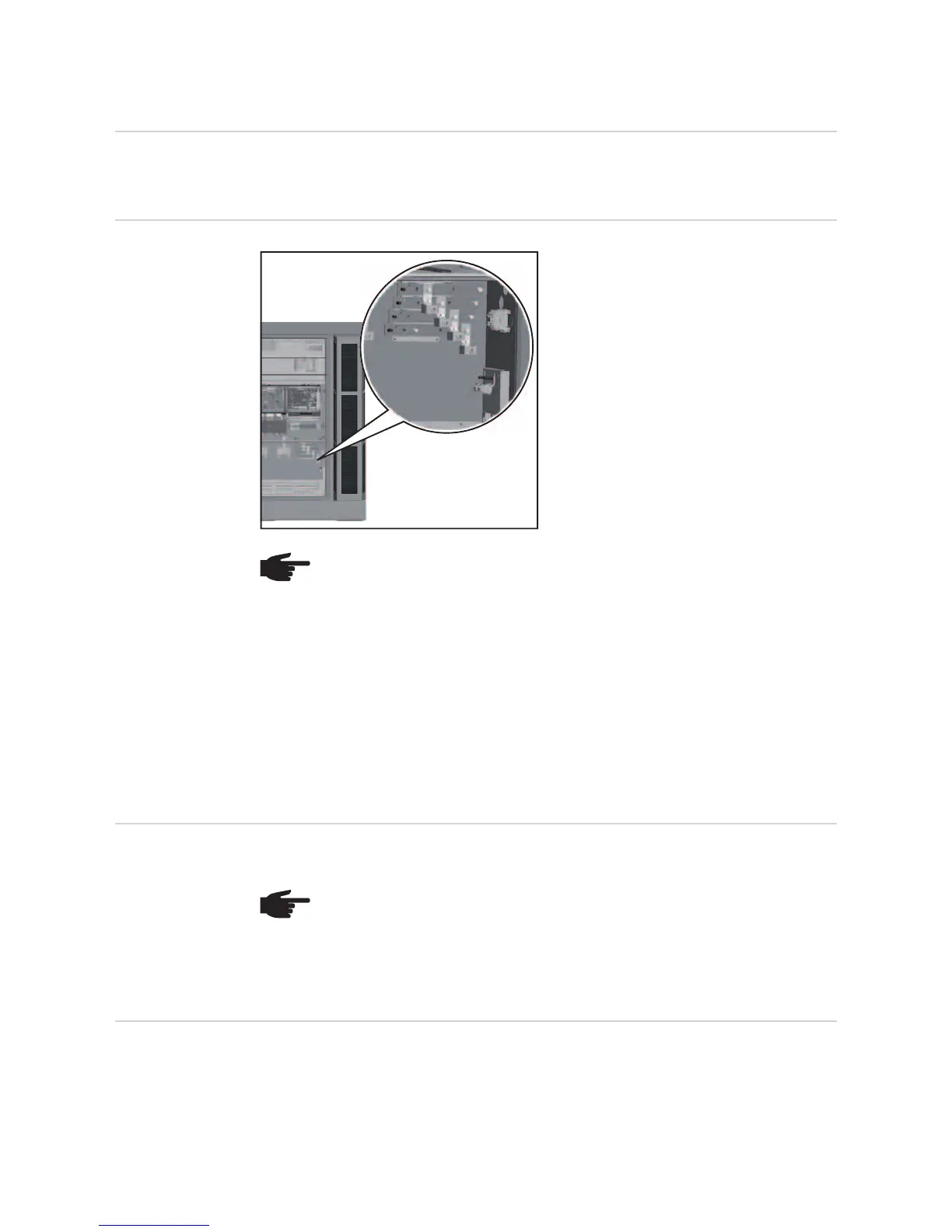
Mains connec-
tions
Legend:
L1 Phase conductor
L2 Phase conductor
L3 Phase conductor
N Neutral conductor
PE Ground conductor / grounding
IMPORTANT! Only the following cables may be connected to V-type terminals:
- RE (round single-wire)
- RM (round multi-strand)
- SE (sector-shaped single-wire)
- SM (sector-shaped multi-strand)
- fine-core cables, in conjunction with ferrules only
Fine-core cables without ferrules may only be connected to the M10 threaded bolts of the
mains connections using a suitable M10 cable lug;
tightening torque = 18 Nm
Connecting alu-
minium cables
Aluminium cables can be connected to the mains connections.
Max. cross-sec-
tion of AC cables
The max. cable cross-section of AC cables when feeding them in from below is 240 mm².
L1
L3
L2
N
M10
PE
NOTE! Ensure that the grid neutral conductor is grounded.
NOTE! When connecting aluminium cables:
- observe national and international guidelines regarding the connection of al-
uminium cables
- follow the instructions of the cable manufacturer
- check every year that the cables are securely attached in accordance with
the specified torque.