47
EN
Grounding the solar modules in the inverter
General Some manufacturers of solar modules stipulate that the module must be grounded.
Locking ring for solar module grounding on the negati-
ve pole
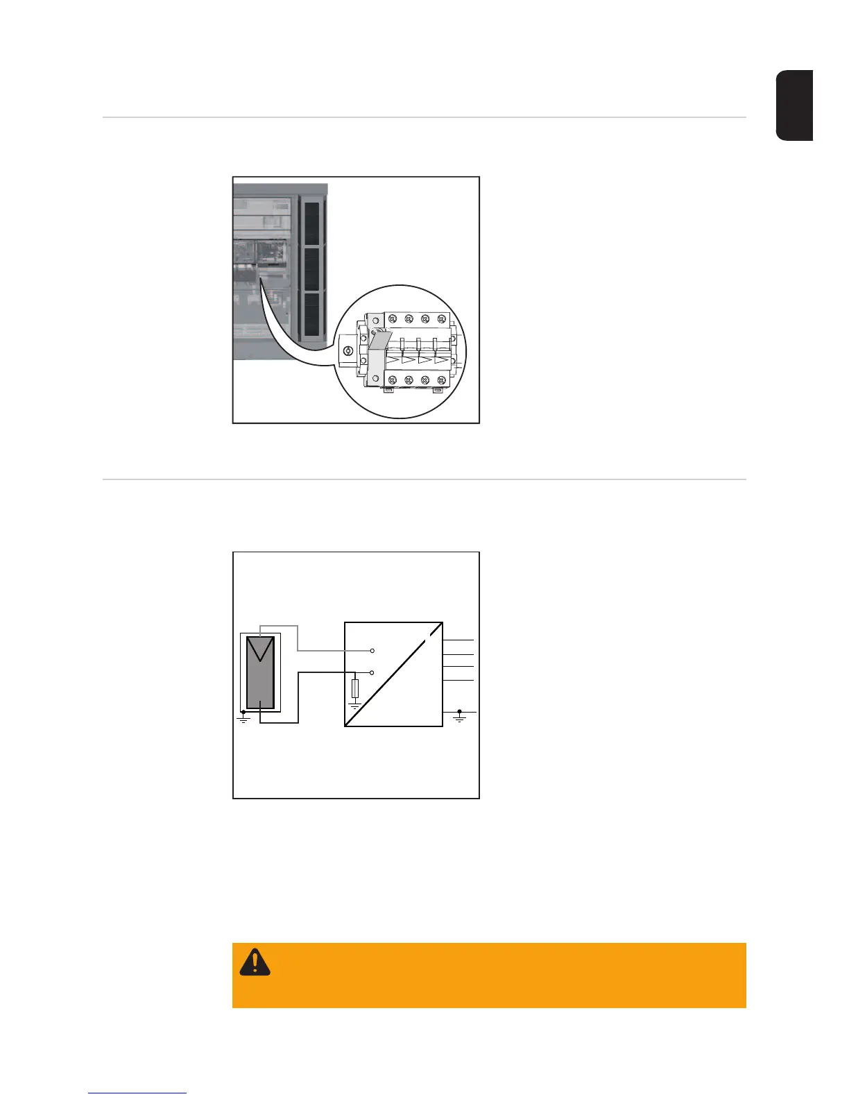
Inside the inverter is a means for grounding
solar modules to the negative pole via a fu-
se.
Grounding the
solar module to
the negative pole
via a fuse
Fronius recommends the following fuse when grounding the solar module to the negative
pole:
nominal current rating 3 A / 1000 V, fuse dimensions 10 x 38 mm
IMPORTANT! Fuses for grounding the solar module are not part of the scope of supply of
the inverter. If the manufacturer of the solar module stipulates that grounding is required,
an appropriate fuse must be ordered separately
Grounding the solar module to the nega-
tive pole via a fuse
(1) Solar module
(2) Inverter
(3) Fuse
WARNING! An electric shock can be fatal. Danger of electric shock if the solar
module is not grounded or is not grounded properly.
To comply with IEC 62109-2, any grounding required by the manufacturer of the
solar module within the inverter must only be carried out via the specified fuse.
DC+
DC-
N
PE
(1)
(2)
=
~
=
~
(3)
L1
L2
L3