39
EN
5
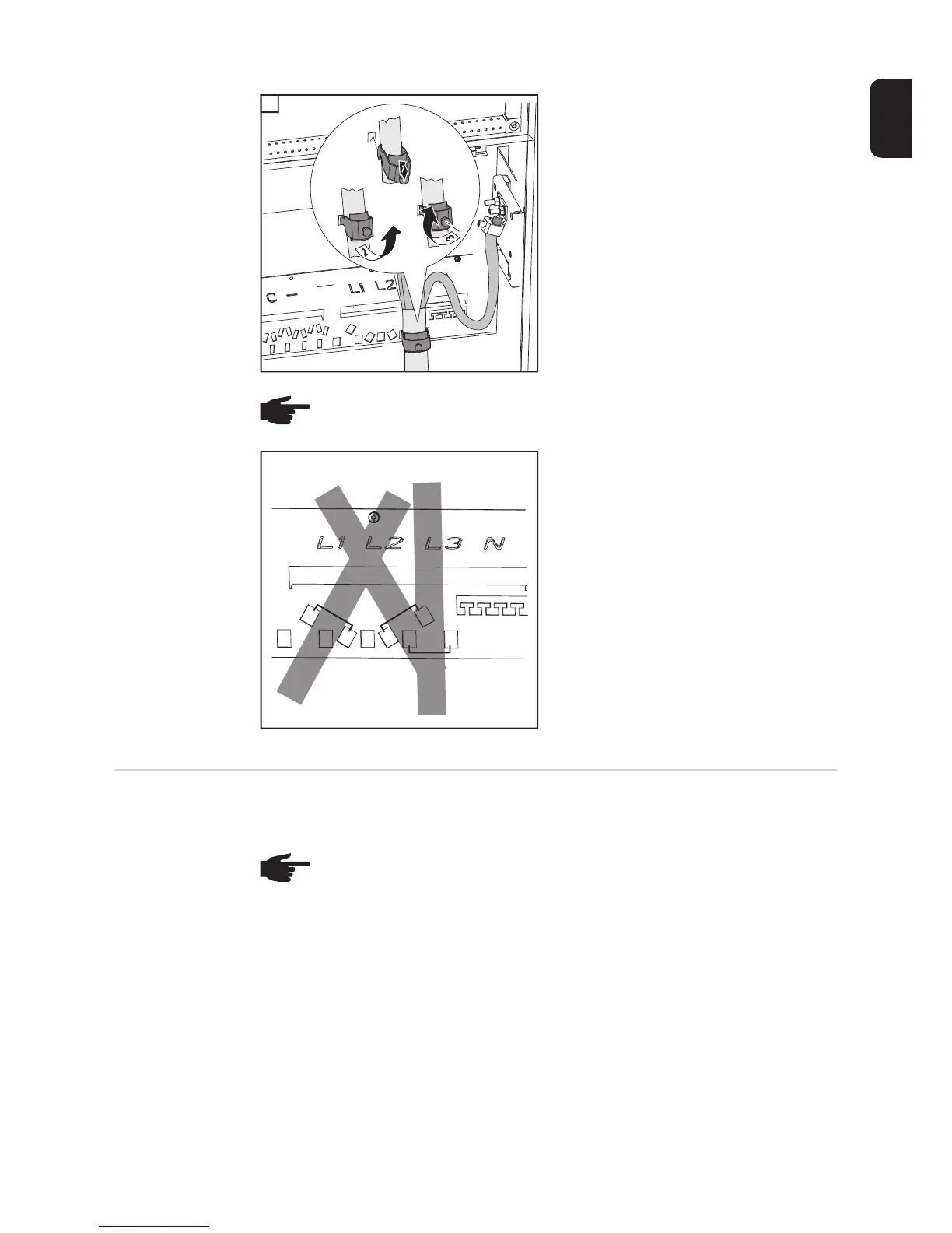
- Place the AC cable in the clamp of the
strain-relief device
- Attach the clamps of the strain-relief
device to the rail
- Secure the AC cable with the clamps of
the strain-relief device
e.g.:
A cable routed at an angle from the
bottom right - attach the clamp for
the strain-relief device to positions
3 and 4
B cable routed at an angle from the
bottom left - attach the clamp for the
strain-relief device to positions 1
and 2
C vertical cable routing - attach the
clamp for the strain-relief device to
positions 5 and 6
Connecting AC
cables with a ca-
ble lug
Alternatively, an AC cable with a cable lug can be connected to the M10 threaded bolts on
the mains connections in order to connect the AC cables to the V-type terminals.
5
NOTE! Different openings are available on the rail for attaching the clamps of the
strain-relief device, depending on the cable routing.
1
A
B
C
2
4
6
3
5
NOTE! Ensure that the phases are connected in the right order: L1, L2, L3, N and
PE.
After connecting the phases, check the rotary field of the grid using a rotary field
measuring device. The inverter is designed for a clockwise rotary field.