116
Removing the primary power module
from the replacement packaging:
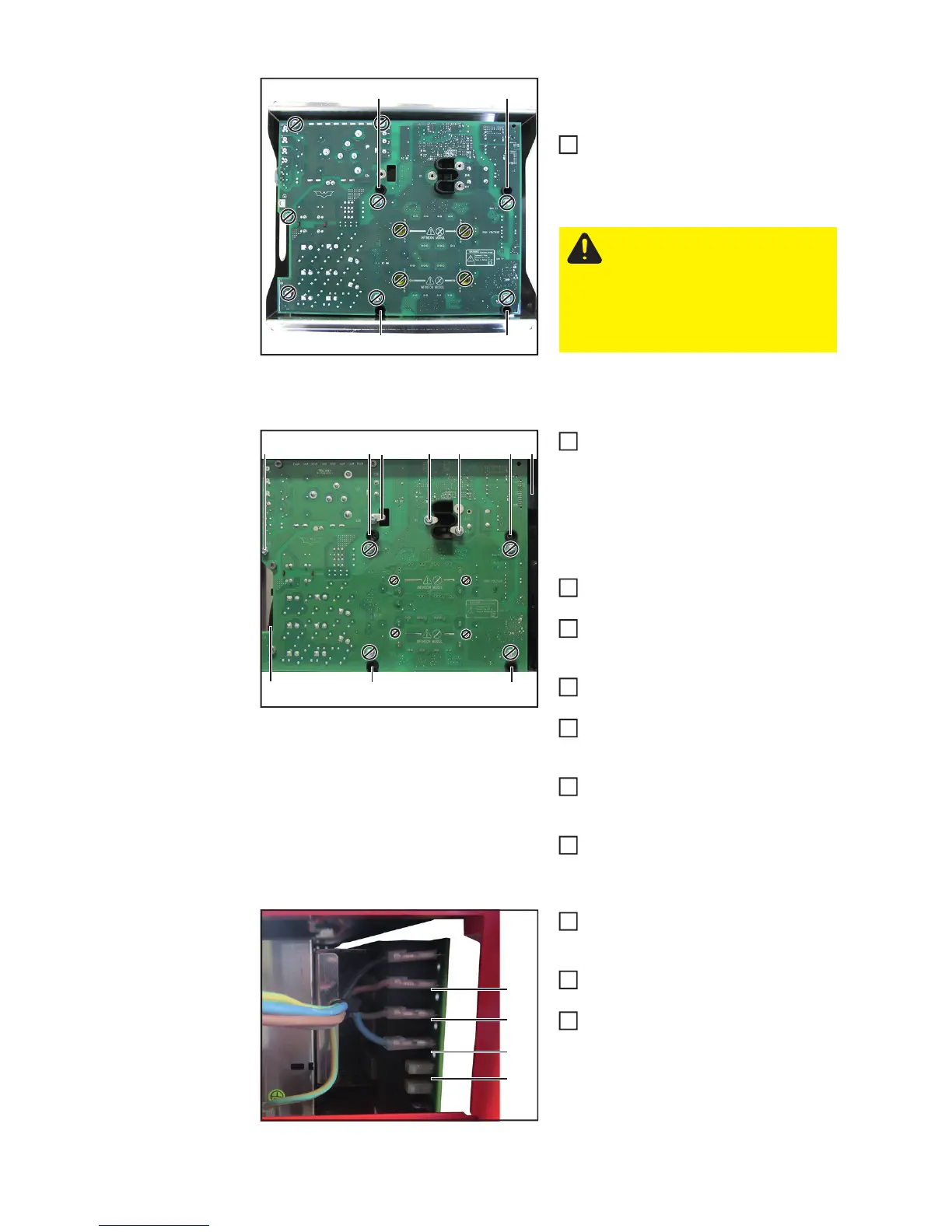
Undo the four 5x10 TX25 tapping
screws (8) and remove the primary po-
wer module from the packaging frame
Installing the primary power module:
Place the new primary power module
in position
- Make sure that the transformer
connection (3) and the inductor
connection (2) are correctly threa-
ded in
- Establish the PFC inductor
connection to the primary rectifier
Now fully insert the primary power mo-
dule and position it correctly
Insert the axial fan (5) in the strain-re-
lief device provided and connect it to
the primary power module
Establish the ribbon cable connection
(4) to the P-control
Fit the primary power module with five
5x10 TX25 tapping screws (1)
[3 Nm]
Fit the transformer connection with two
5x10 TX25 tapping screws (3)
[4.5 Nm]
Fit the inductor connection with one
5x10 TX25 tapping screw (2)
[4.5 Nm]
Connect the mains cable (L1, L2, L3,
N) to the primary power module in the
correct sequence
In case the assembly aid has been
mounted, remove it
Fit the front panel and the AC connec-
ting plate (see the "Closing the device"
section)
(8)
(8)
(8) (8)
CAUTION! The faulty primary
power module must be screwed
into the replacement packaging
and returned to Fronius! No guar-
antee or warranty claims can be
made if the item is not returned
properly!
1
(5)
(4)(1)
(1)(1)
(1)(1) (2) (3) (3)
1
2
3
4
5
6
7
(L1)
(L2)
(L3)
(N)
8
9
10
 Loading...